The XGS 136
Measured on a Sophos XGS 136. Where a fact is known to generalise across the range it says so;
where it is not, assume it does not. This page is the appliance as an object: what it is, what
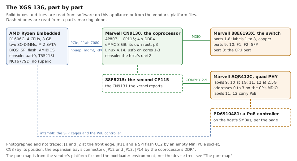
FreeBSD sees of it, how to tell the board from software, the fourteen ports, and the board
photographed part by part. The driver it runs is contrib/npuep, and the protocols that driver
speaks are the pages under npuep/.
What it is
Two computers in one box, like the rest of the range:
host         AMD Ryzen Embedded R1606G (x86), 4 CPUs, 8 GB, a SATA drive on M.2, OPNsense on it
coprocessor  Marvell CN9131 (AP807 + two CP115, ARM), its own Linux, its own eMMC
link         PCIe 11ab:7080, Gen3 x4: BAR0 1 MB, BAR2 16 MB, BAR4 16 MB; MSI-X 16; 6 VFs
front        fourteen ports: labels 1 to 8 behind an 88E6193X switch, F1 and F2 on the same
             switch, labels 9 to 12 on an AQR412C quad PHY - all behind the coprocessor
assembly     AMDA0201-0003 inside the SMBIOS serial; AMDA0201 in the USB bridge's EEPROM
Where each part is written up
| part | page |
|---|---|
| getting the coprocessor out of reset, over the USB-to-SPI bridge | npuep/npu-bring-up.md |
| what the coprocessor publishes into its BARs, and the handshake | npuep/facility-protocol.md |
mvmgmt0, the management link |
npuep/mvmgmt.md |
| the datapath that carries the fourteen ports, and its header | npuep/giu.md |
| the control channel and the forwarding tables | npuep/rpc.md |
| per-port state: link, media, address | npuep/netagent.md |
| the family, and what has run on which board | families/armada.md |
| the three parts and the channels, drawn | the-road.md |
| the photographs | images/hardware/xgs136/ |
| measurements | none from this appliance yet; measurements/ says so |
What FreeBSD sees on the host
Working with no driver work at all:
CPU    AMD Ryzen Embedded R1606G, 4 CPUs (1 package x 2 cores x 2 threads)
RAM    8192 MB
Disk   ahci0 -> ada0, SATA 3.x
USB    xhci0, USB 3.0
SMBus  intsmb0 -> smbus0 (AMD FCH)      the I2C path to the SFP cages and the PoE controller
HID    Microchip MCP2210 USB to SPI Master -> usbhid0 -> hidbus0
serial uart0 0x3f8 (console) and uart2 0x3e8 (the NPU's console, needs a hint)
Not working, and it is the whole reason this repository exists:
There is also no superio, so the NCT6779D hardware monitor - which the BIOS reads perfectly
well - is invisible to a stock FreeBSD. That is a separate piece of work.
The way in before the ports: a USB network adapter
Until npuep brings the front ports up, the host has no network of its own: every port belongs to
the coprocessor, and pci1 above is the only network device on the bus. So the first network this
appliance had under OPNsense was a USB Ethernet adapter - and it stays the one way in that does not
depend on the coprocessor at all, which is exactly what a driver under development needs.
porting-notes.md says why it is worth reaching for one early.
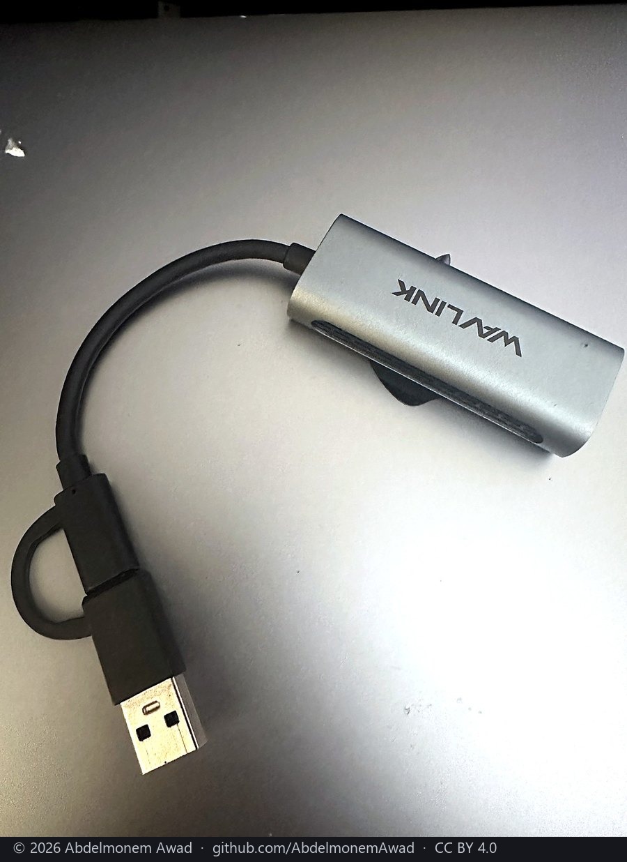
The one in use here, after several were tried:
 |
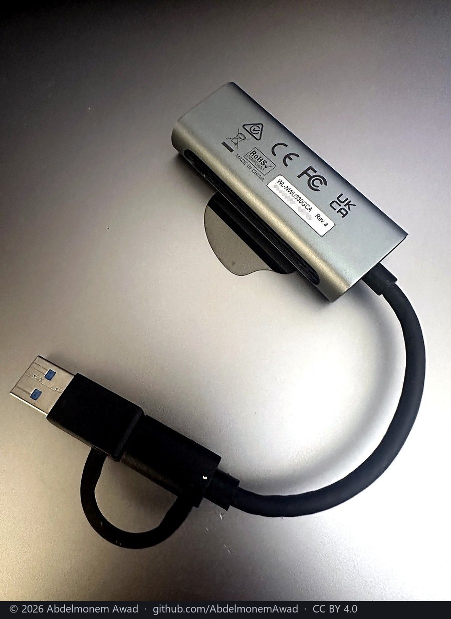 |
| maker | WAVLINK - the product page |
| model | WL-NWU330GCA, Rev.a |
| host side | USB 3.2 at 5 Gbps, on a hybrid cable: USB-C, with a USB-A adapter tethered to it |
| network side | one RJ45, 10/100/1000 Mbit/s and 2.5 Gbit/s; the light green at 2.5G and amber below it |
| chip | a Realtek RTL8156, by the retailers' listings - RTL8156B on one, RTL8156 on another; the maker's page does not name it |
| under FreeBSD | ure(4), in the stock kernel, which lists the RTL8156, RTL8156B and RTL8156BG at up to 2,500 Mbit/s; the adapter appears as a ue interface with nothing to install |
Two identical adapters are one too many. With two of the same model on this appliance - LAN on
one, WAN on the other - the two traded names across a warm reboot, and the box served its LAN
address on the WAN cable and asked for an address on the LAN one: healthy, and unreachable. It looks
exactly like a reboot that hung. Both adapters report the same USB serial number from the factory, so
nothing but the root-hub port each sits in tells them apart, and FreeBSD's ue numbering does not
follow the port. One adapter has nothing to swap with.
Other adapters whose chip FreeBSD names
Not tested here. Each is listed because its maker's own page names the chip and a FreeBSD driver in the stock kernel lists that chip; the photographs are on the makers' pages.
| adapter | the chip, as its maker states it | speed | FreeBSD driver | maker's page |
|---|---|---|---|---|
| Plugable USBC-E2500 | Realtek RTL8156B | 2.5 Gbit/s | ure(4) |
plugable.com |
| TP-Link UE300 | Realtek RTL8153 | 1 Gbit/s | ure(4) |
tp-link.com |
For a gigabit adapter on an ASIX chip the driver is
axge(4),
which lists the AX88179, AX88179A and AX88178A; a phone or anything else that presents itself as a
standard CDC network device is
cdce(4).
The same product name can hide a new chip. Retail listings of Plugable's USB3-E1000 name an ASIX AX88179; the maker's page now names the AX88179B, which
axge(4)does not list, and Plugable itself does not recommend that adapter for FreeBSD or pfSense. Check the chip on the maker's page, and once it is plugged in, check whatusbconfiganddmesgsay attached, before trusting an adapter with a firewall's only way in.
The endpoint
pci0:1:0:0   vendor=0x11ab device=0x7080   class=network/ethernet
  bar[10]  1 MB    64-bit
  bar[18]  16 MB   64-bit
  bar[20]  16 MB   32-bit
  PCIe     x4 @ 8.0 GT/s (Gen3)
  MSI      32 messages;  MSI-X 16 messages, table in BAR0 @0x1000, PBA @0x1800
  SR-IOV   VF device ID 0x7081, 6 VFs supported
  ARI, AER, LTR, TPH Requester, Resizable BAR, L1 PM Substates
The link is Gen3 x4, about 32 Gbit/s. All fourteen front ports together are about 17 Gbit/s at most - eight switch ports and labels 9 and 10 at 1G, labels 11 and 12 at 2.5G, and the two SFP cages at 1G - so the roughly 936 Mbps single-port ceiling reported by other projects on this hardware is not a PCIe bandwidth limit, and neither is an MTU of 1500. Whatever causes them is above the bus.
The SR-IOV capability reports 6 VFs where the vendor's Linux exposes 8 in sysfs. Unresolved, and recorded because it is the sort of discrepancy that wastes a day later.
Identifying the board from software
Two independent sources, and the second is the more useful one.
SMBIOS is awkward. smbios.planar.product is the generic string XGS across the whole
range and smbios.planar.version is not the model either. The assembly number is buried inside
smbios.planar.serial, in the form:
So anything keying a chassis table off SMBIOS has to match on the serial, not on product or version - and the serial also carries the unit's own identity, which is worth remembering before putting it in a log.
The MCP2210's EEPROM is better for this purpose. Bytes 0 and 1 hold the assembly number as
(byte0 << 8) | byte1, so 0x00, 0xC9 is 201, which is AMDA0201. It is on the host side, needs
no I2C, and answers while the coprocessor is held in reset.
The coprocessor
SoC       Marvell CN9131  (AP807 + two CP115)
storage   its own eMMC, 7.28 GiB, four partitions, root on p3
firmware  U-Boot 2019.10-10.22.03, Linux 4.14.207-10.22.03
model     the kernel reports "Sophos XGS126/136" - one board for both
cmdline   console=ttyS0,115200n8 root=/dev/mmcblk0p3 cpuidle.off=1
          isolcpus=1-3 nohz_full=1-3 rcu_nocbs=1-3
The CN9131's second CP115 is what lets this board drive fourteen ports where the nine-port model in the same family uses a CN9130.
Three cores are isolated from the scheduler and run the dataplane; that is what isolcpus=1-3
is for.
The coprocessor boots from its own storage, not from the host's disk. Replacing the host SSD
- which is what running OPNsense on one of these means - does not touch its firmware at all, and that is what makes the whole exercise reversible.
The port map
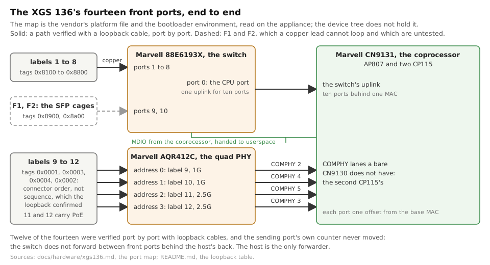
Fourteen ports, all behind the coprocessor. The switch is an 88E6193X LinkStreet; the multi-gig ports are on an AQR412C quad PHY.
labels 1-8   ->  switch ports 1-8      (88E6193X, CPU port is port 0)
label 9      ->  CN9131 COMPHY 2       (AQR412C address 0, 1G)
label 10     ->  CN9131 COMPHY 4       (AQR412C address 1, 1G)
label 11     ->  CN9131 COMPHY 5       (AQR412C address 2, 2.5G + PoE)
label 12     ->  CN9131 COMPHY 3       (AQR412C address 3, 2.5G + PoE)
F1, F2       ->  switch ports 9, 10    (SFP)
Each port takes one offset from the board's base MAC, in that order.
The device tree is not where this map lives, which is worth knowing before going looking for it there. Neither the 9130 nor the 9131 device tree contains a switch node, a DSA node, an AQR412C node or any PHY child: both MDIO controllers per CP are declared empty and handed to userspace. The map comes from a platform text file in the coprocessor's firmware plus the bootloader environment.
The board, photographed
Photographed on 2026-10-11, the XGS 136 out of its case. Everything above was read over a wire
or out of a file; this is the same board, and the pictures put a part under each of those
readings. Serial numbers, barcodes and the storage's label are pixelated with
tools/blur-labels.py; part markings and reference designators are left, because they describe
the design and not this unit. The private-data checker cannot read a photograph, so that tool is
the only gate. The photographs of each appliance are in a folder of their own under
docs/images/.
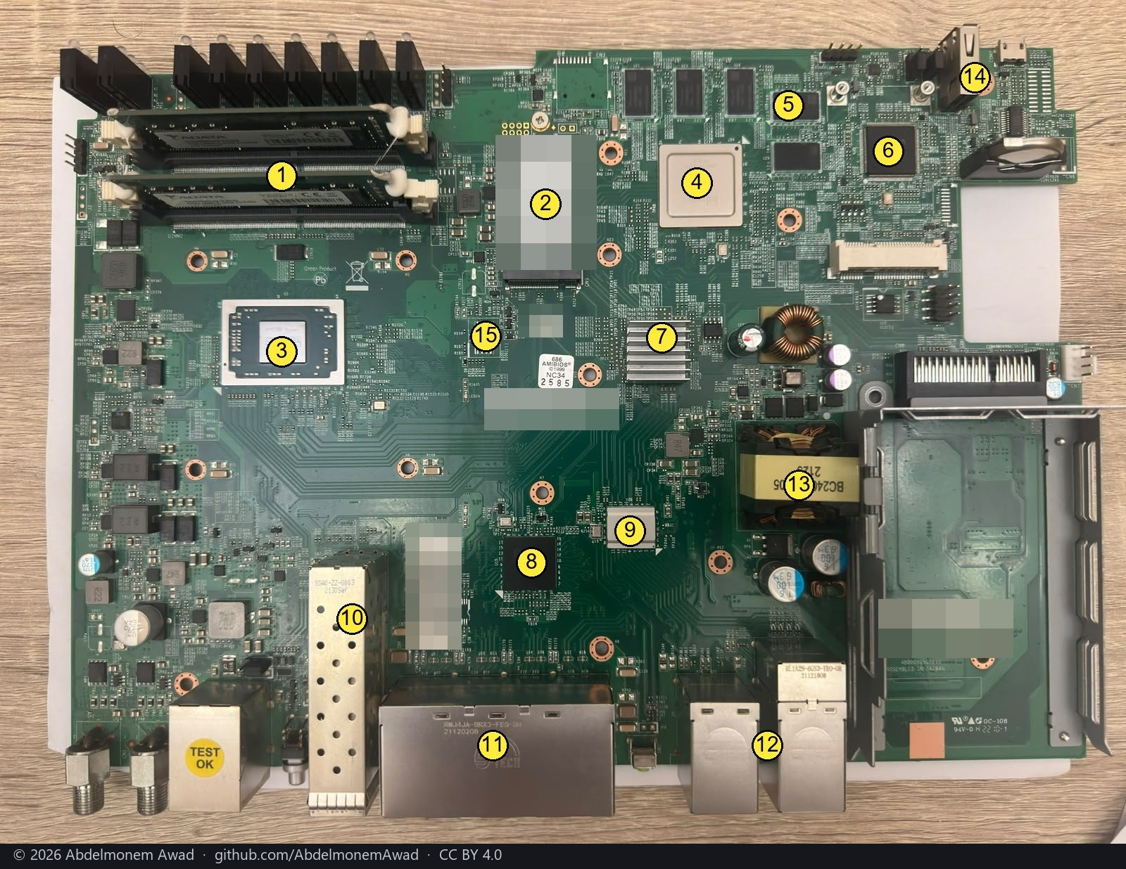
| 1 | the host's two SO-DIMMs | 9 | AQR412C, the PHY behind labels 9 to 12 |
| 2 | the host's M.2 SATA drive | 10 | the SFP cages, F1 and F2 |
| 3 | AMD Ryzen, the host | 11 | the eight copper ports, labels 1 to 8 |
| 4 | CN9130, the coprocessor, under its lid | 12 | labels 9 to 12, two of them with PoE |
| 5 | the coprocessor's four DDR4 chips | 13 | the PoE transformer |
| 6 | NCT6779D, the Super I/O | 14 | the console and USB at the back |
| 7 | the coprocessor's heatsink | 15 | the BIOS flash, under the AMIBIOS sticker |
| 8 | 88E6193X, the switch behind labels 1 to 8 and the cages |
The numbers are placed by eye on the photograph; each part is named from its marking in the close-ups below, and tied to what software sees where the sections above say so.
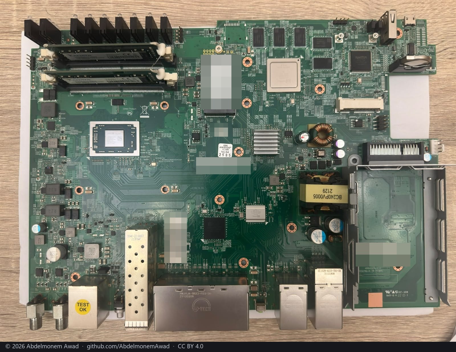
The same board unmarked. The assembly's label is at the bottom right; AMDA0201 is what the
EEPROM says and what the sections above read.
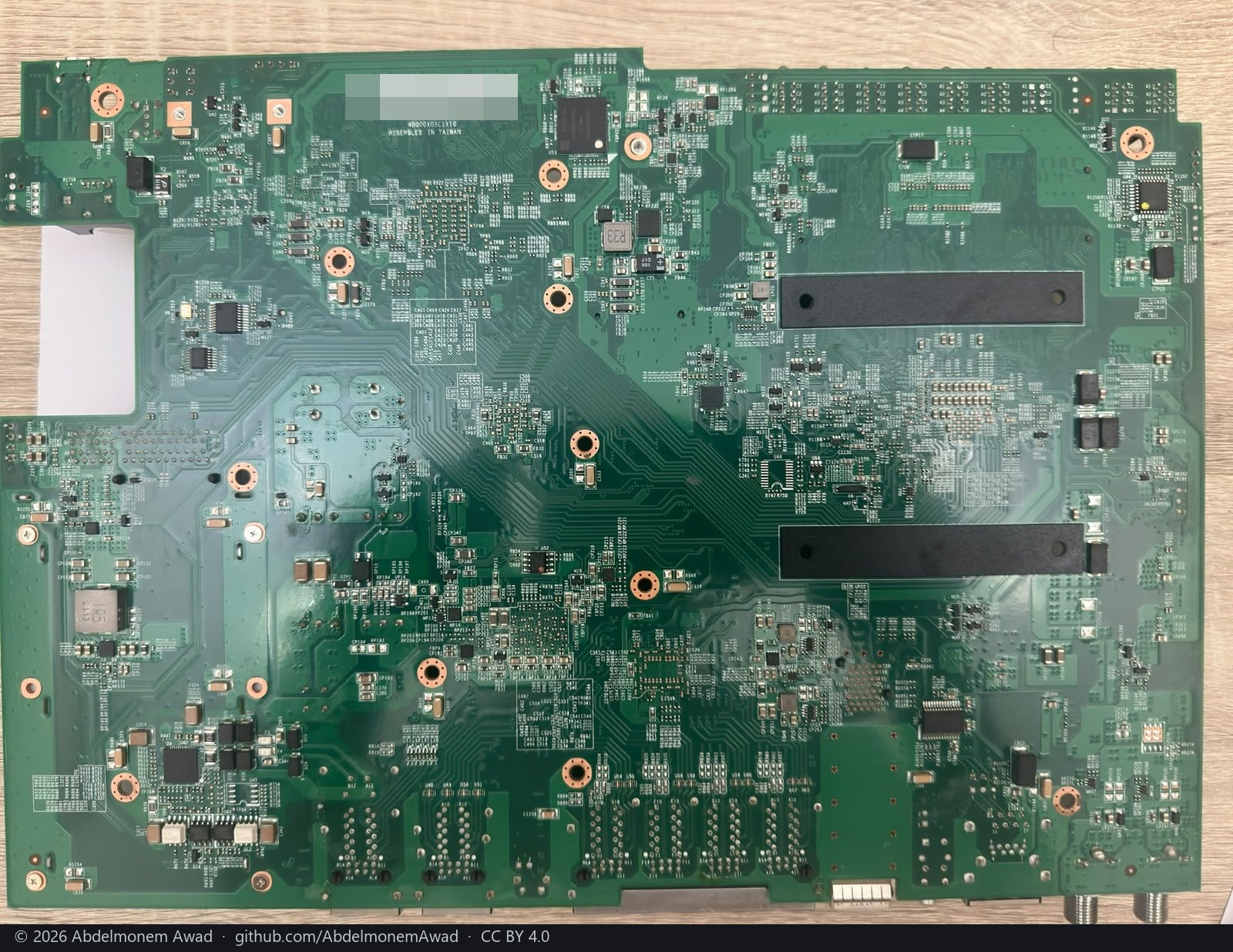
From below: no active part of note - the two black bars are the DIMM and M.2 retainers' backs - and the assembly barcode at the top left, pixelated.
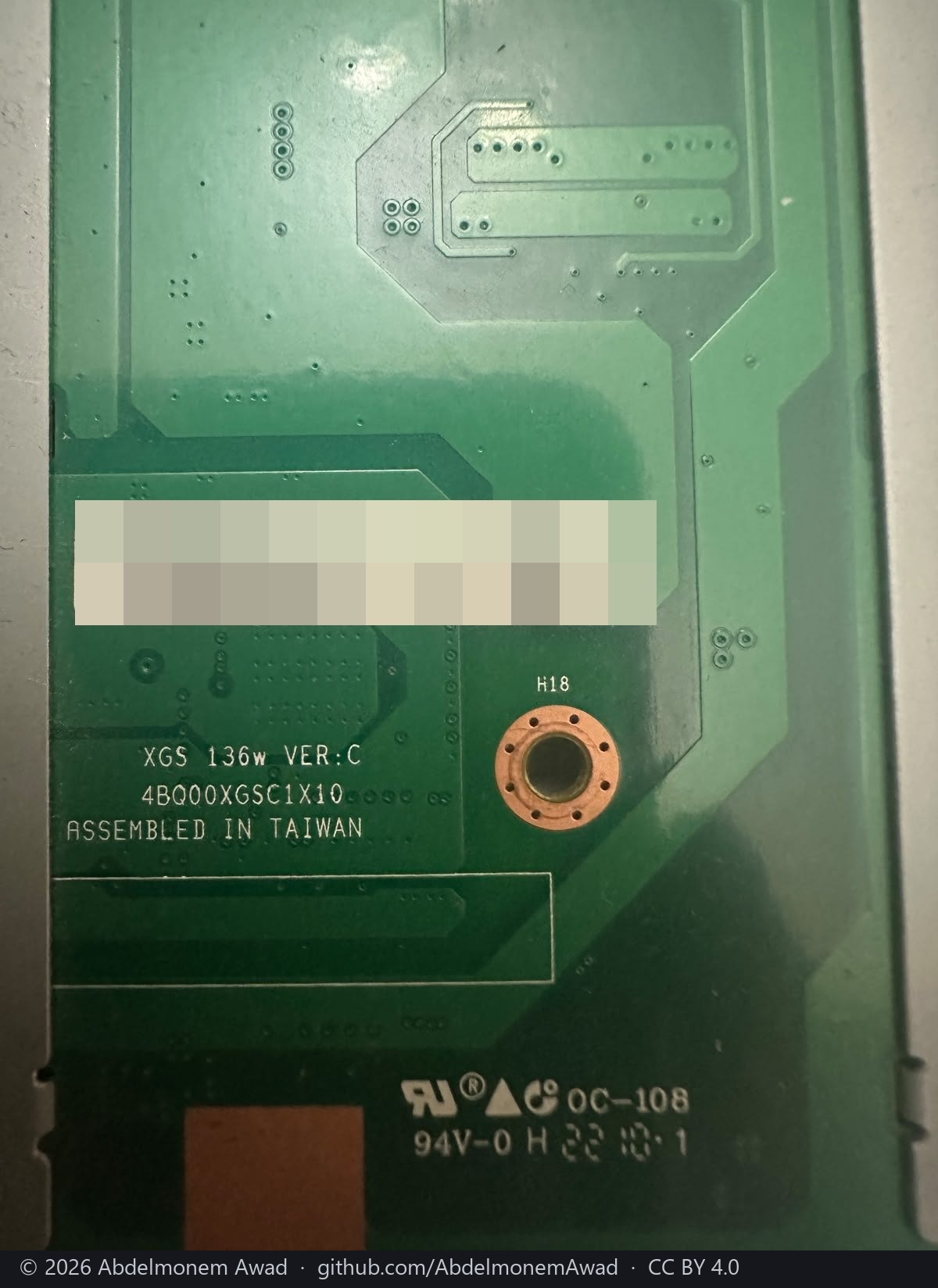
The label and the silkscreen beside it: XGS 136w VER:C, assembled in Taiwan.
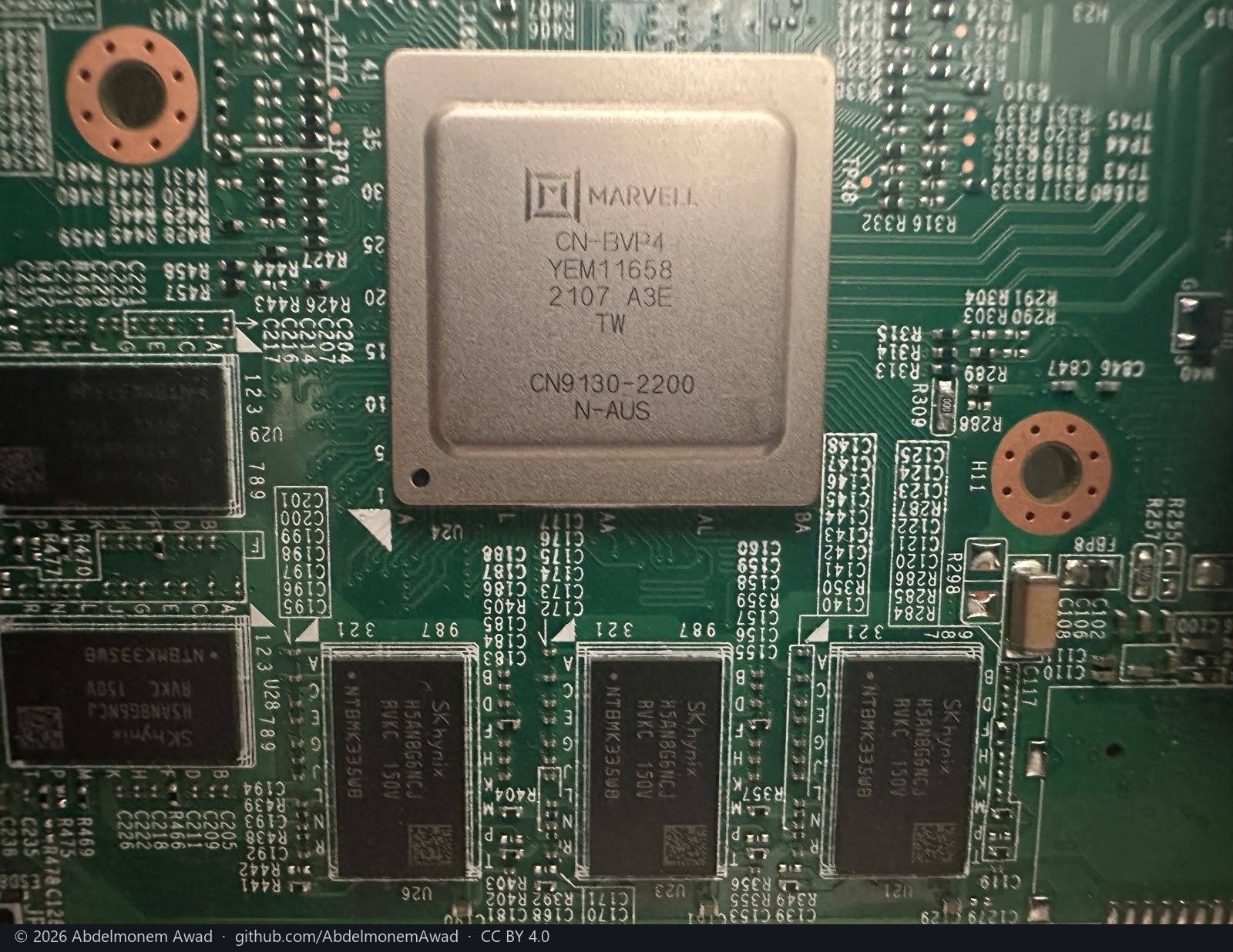
The coprocessor: Marvell CN9130-2200, with four SK hynix H5AN8G6NCJ DDR4 chips around it. The kernel on it reports a CN9131, which is a CN9130 with a second CP115 - and that second part is the next photograph.
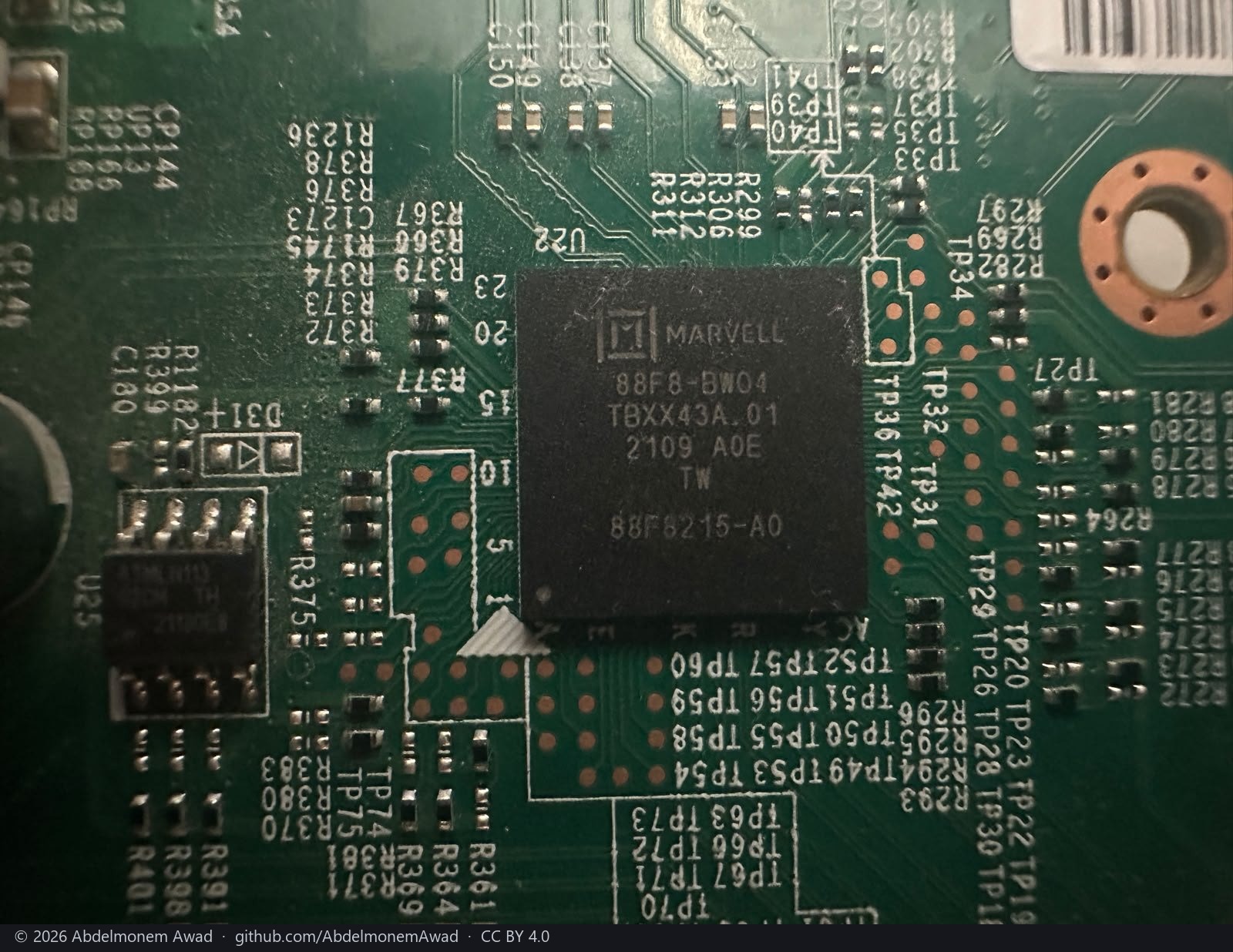
Marked 88F8215-A0, beside an 8-pin Atmel part (U25, an EEPROM by its package and marking).
The port map above puts labels 9 to 12 on CN9131 COMPHY lanes that a bare CN9130 does not have;
this is the part that has them. Read from the marking and the port map, not from a datasheet.
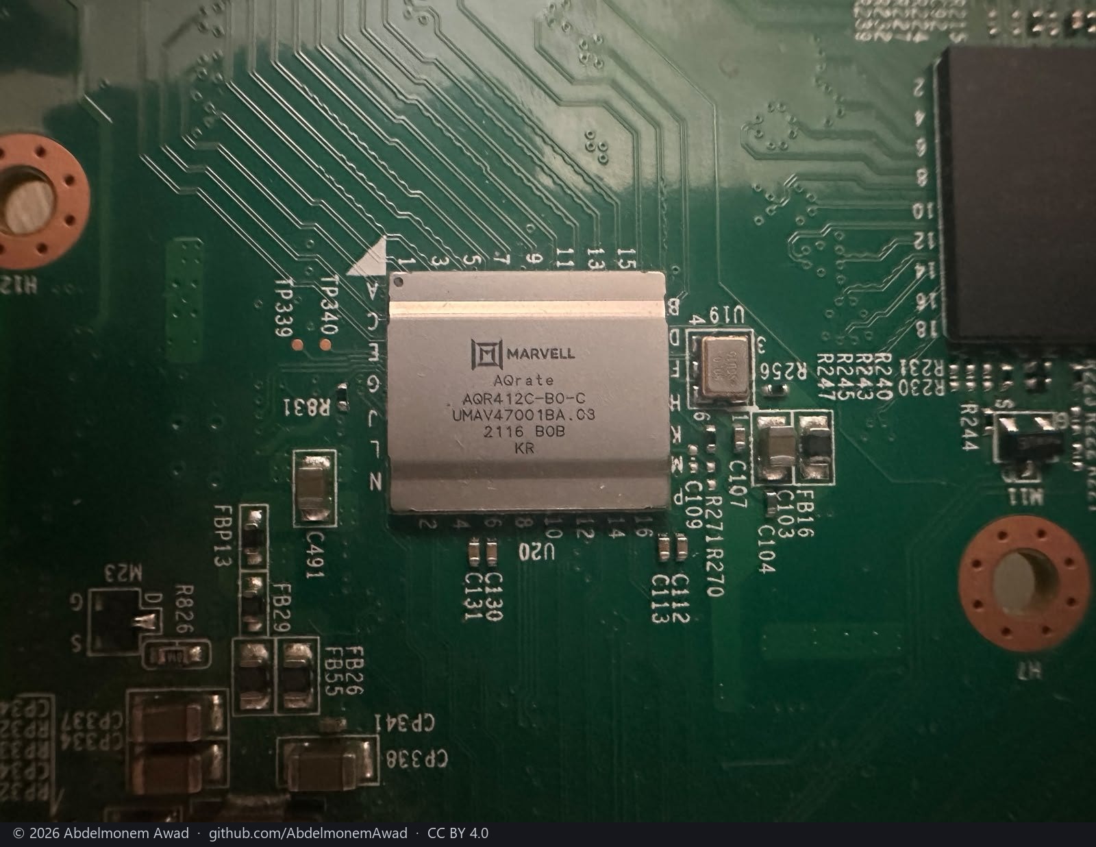
Marvell AQrate AQR412C-B0-C: the quad multi-gig PHY behind labels 9 to 12, two of them at
2.5G with PoE. The crystal beside it is U19.
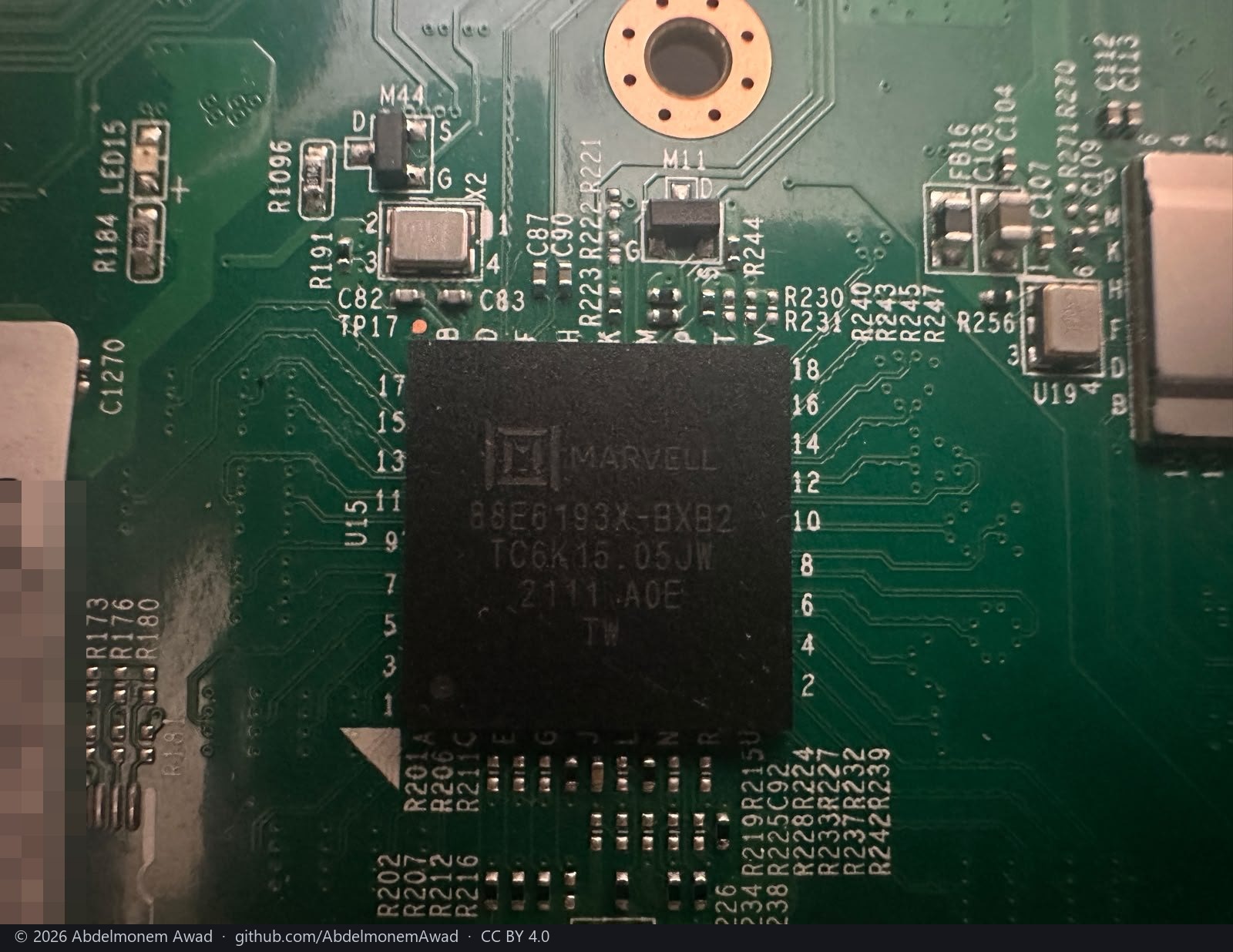
Marvell 88E6193X-BXB2, the LinkStreet switch behind labels 1 to 8 and the two SFP cages (ports 9 and 10 on the switch). The same part as the XGS 3300's, reached there over the coprocessor's MDIO - see the OCTEON TX peripherals.
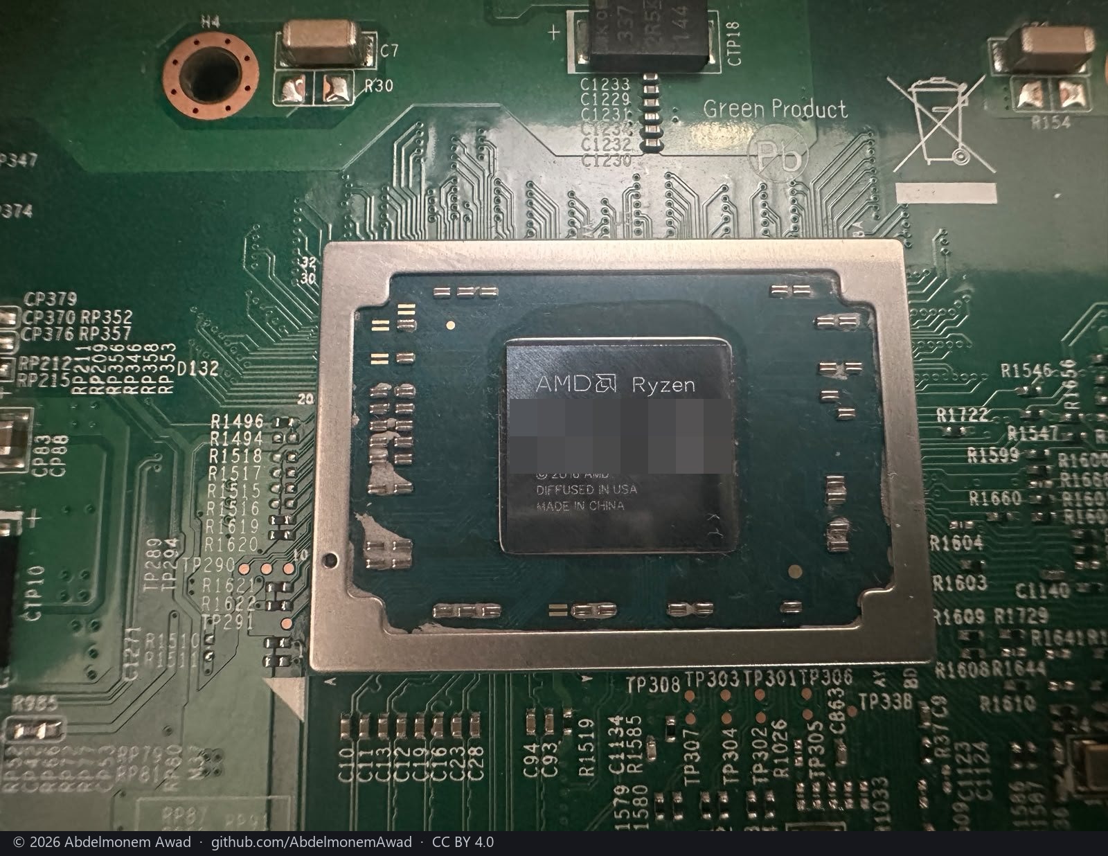
The host: AMD Ryzen Embedded, which FreeBSD reports as an R1606G. Its lot code and matrix are pixelated.
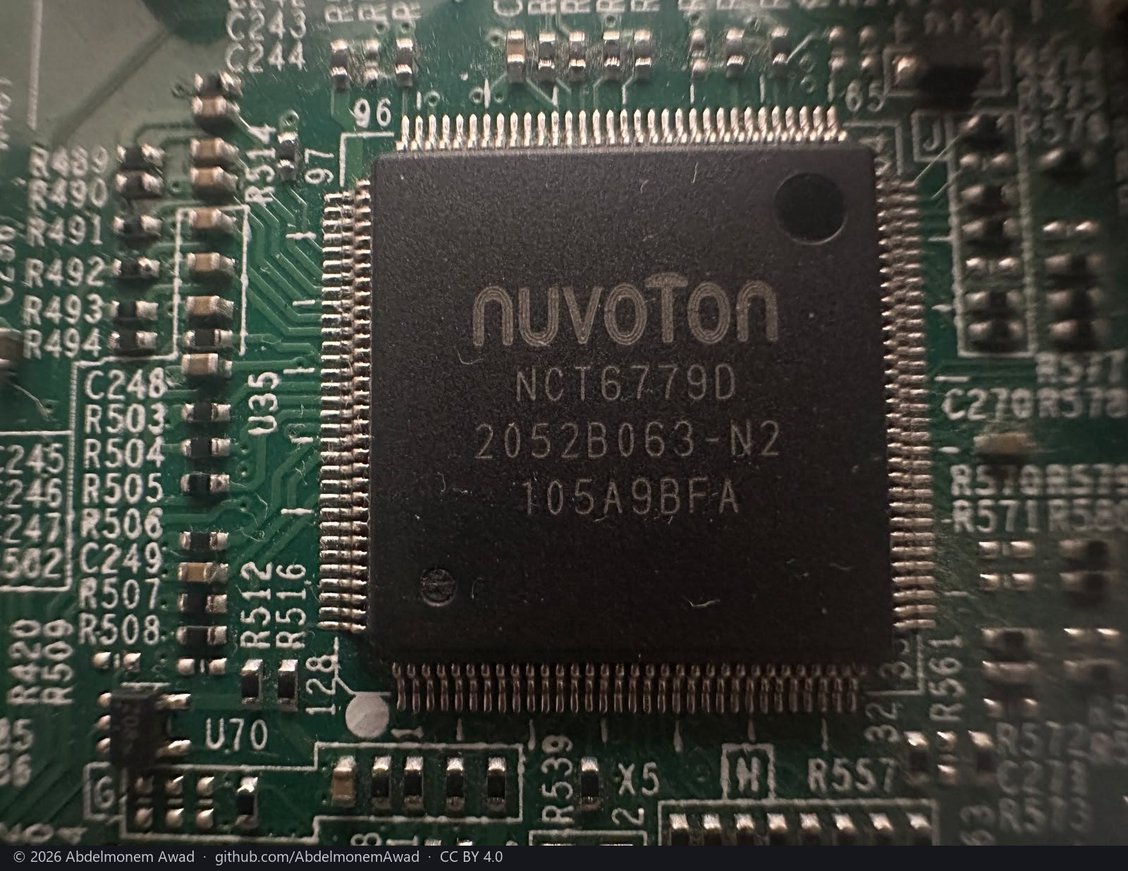
Nuvoton NCT6779D, U35: the Super I/O whose hardware monitor the BIOS reads and a stock
FreeBSD does not, as the first section says. It is the chip os-fanctl knows a table for and
could not find on this board for want of superio(4) - which this photograph settles: it is
there.
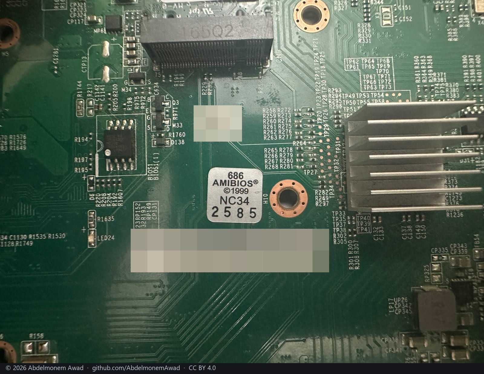
BIOS1, an 8-pin SPI flash beside a second footprint BIOS1(1) that is not fitted; the AMIBIOS
sticker; the assembly's serial barcode, pixelated; and the host's M.2 socket above with its screw
post, its designator cut by the photograph's edge. The heatsink at the right is the coprocessor's.
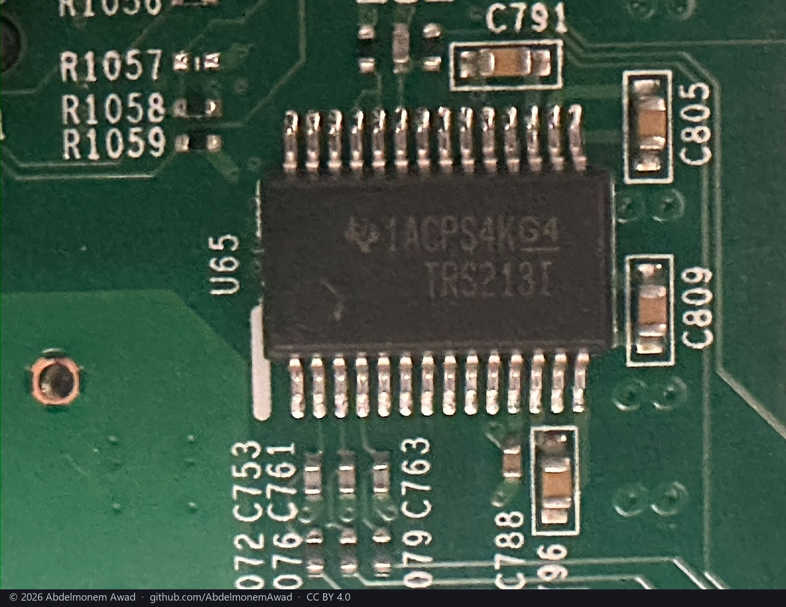
TI TRS213I, U65: the RS-232 transceiver on the host's console. The coprocessor's own console
is the host's third UART, at 115200, and needs a hint; see the first section.
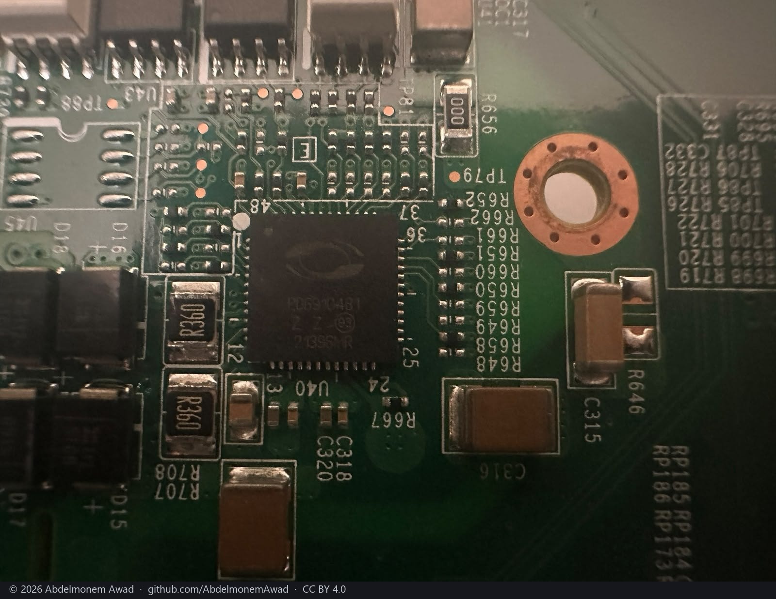
U40, marked PD6910481: by that marking a Microchip PD69104, a four-port PoE controller - the
part behind the "2.5G + PoE" of labels 11 and 12, and what the SMBus path to the PoE controller
in the first section reaches. Identified from the marking only.
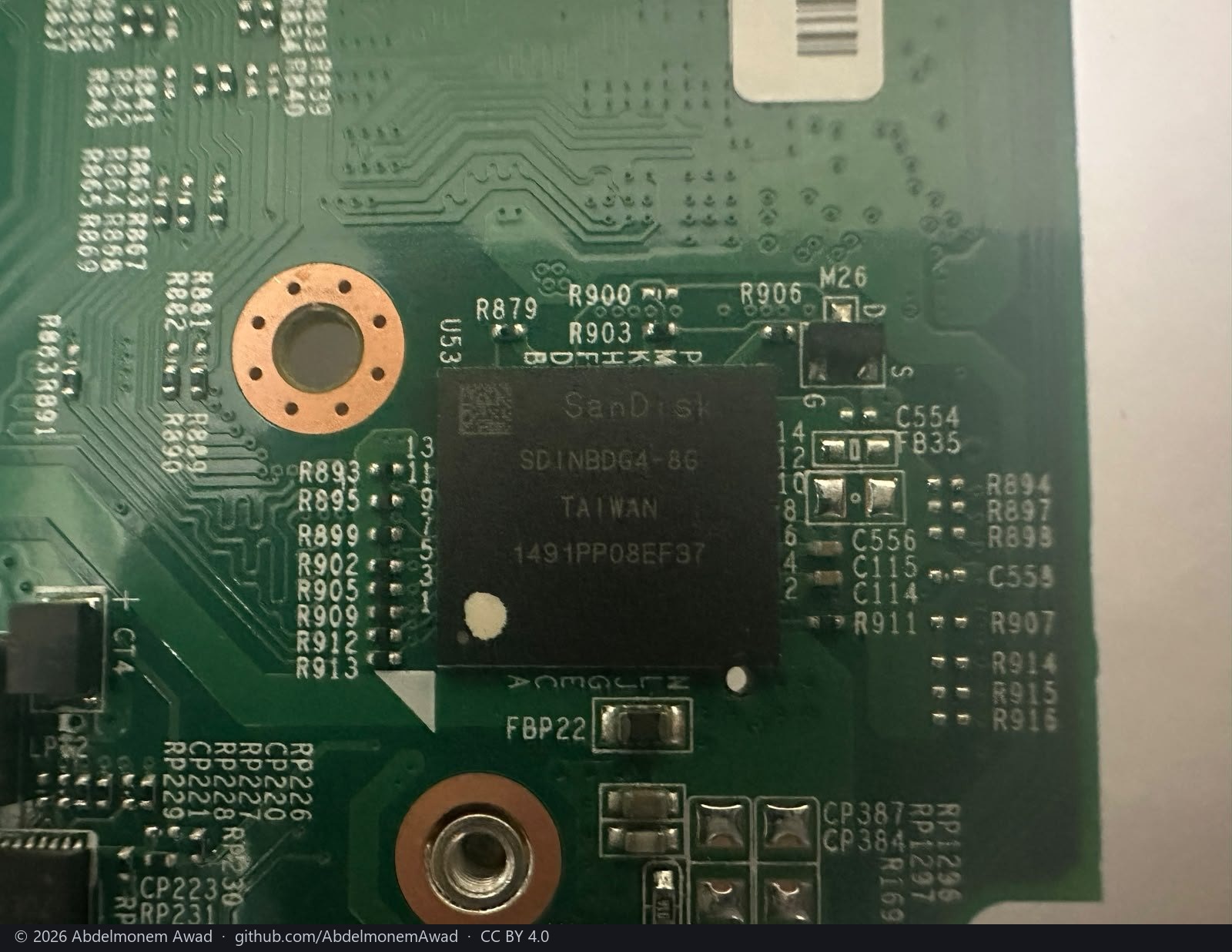
SanDisk SDINBDG4-8G, U53: an 8 GB eMMC. The coprocessor boots from its own storage - 7.28 GiB
in four partitions, as above - and this is the part of that size on the board.
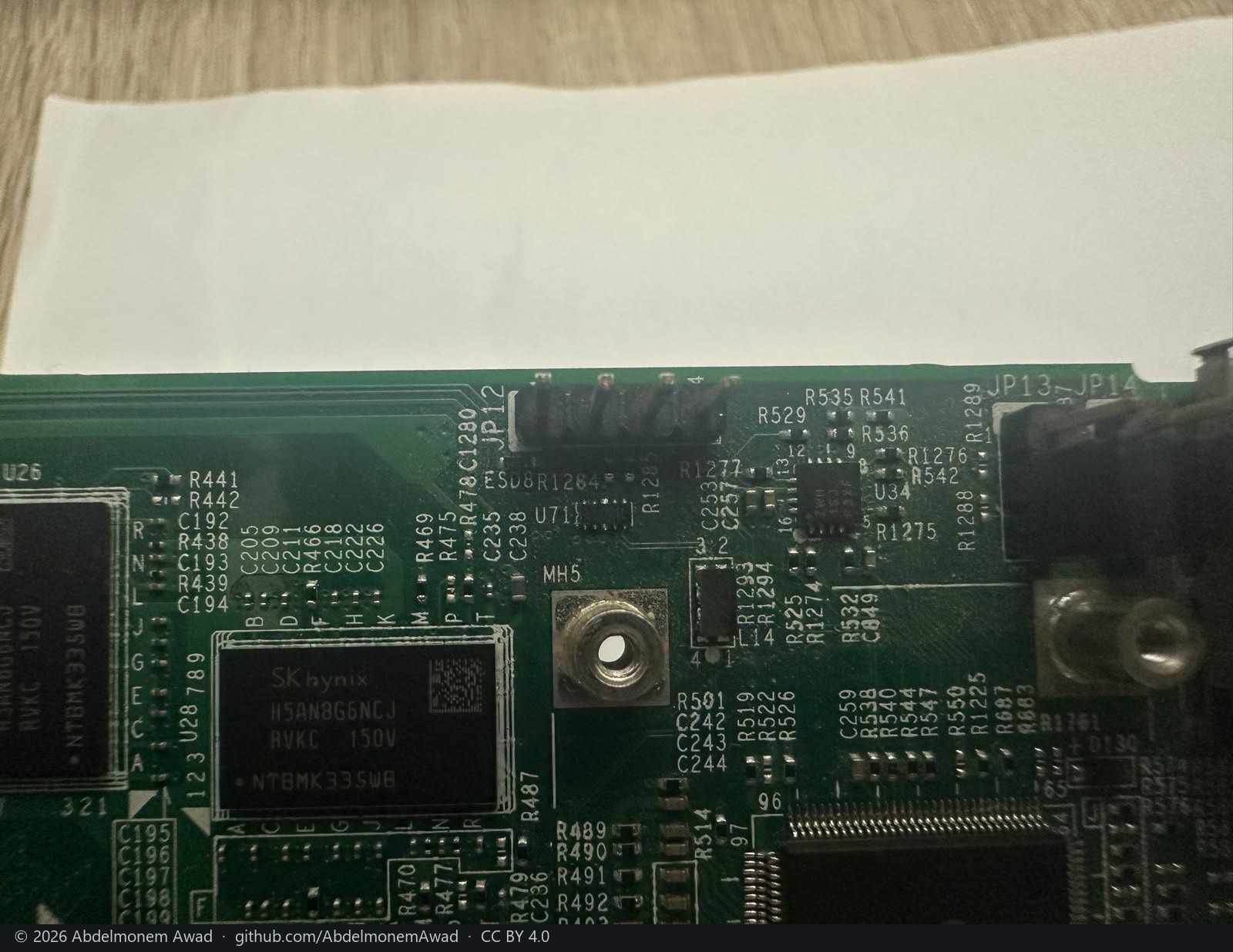
One of the coprocessor's DRAMs, with JP12, a four-pin header, and JP13 and JP14 at the board's
edge. Which of them is the coprocessor's console header was not traced; the XGS 3300 has the same
question answered on its page.
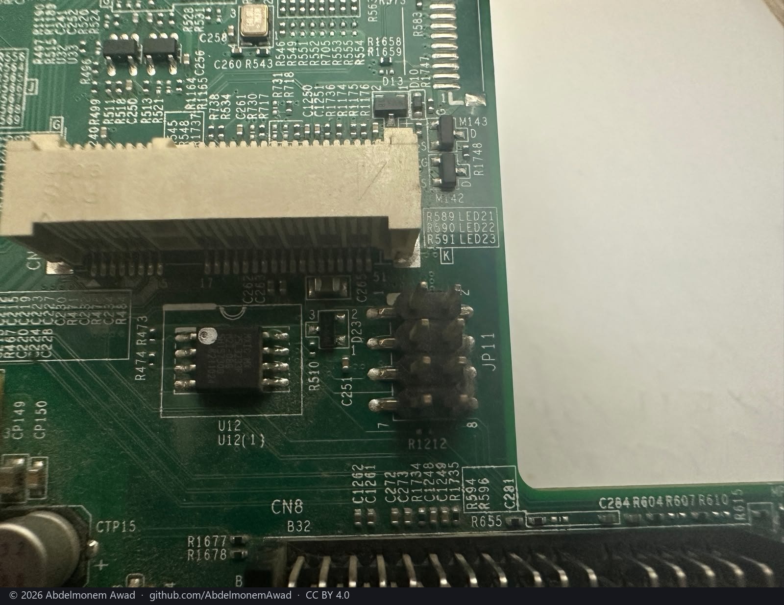
CN8, an M.2 socket with nothing in it
- The white socket is a Mini PCIe socket, not M.2, and it is empty. Its contacts run eight before
the key, then from the silkscreen's
17to its51: the 52-pin layout of a PCI Express Mini Card, keyed after pin 15. An M.2 socket has 75 positions and its keys elsewhere. Its own designator is cut off at the photograph's left edge - onlyCNshows. CN8is the black connector along the bottom of the photograph. Its silkscreen numbers a rowB1toB32, as a PCIe card edge with 32 contacts a side is numbered, and it sits at the edge directly above the expansion bay. By its position it is the bay's connector - the one expansion slot the vendor's datasheet lists, for a 3G/4G or 5G module, an SFP DSL module or, on a w model, a second Wi-Fi radio. Not traced.- What the Mini PCIe socket is for. This board's label reads
XGS 136w, and the vendor's datasheet gives the w models an integrated Wi-Fi 5 radio, 3x3, with three external antennas - the kind of radio that comes on a Mini PCIe card. Under the vendor's own system on this unit, the host's PCI bus showed nothing but the coprocessor and no radio or modem driver was loaded, so the socket was empty then as well. The vendor's system carriesath10kandmt7915efor its radios, and its modem daemon finds a modem by its USB identity (expansion-modules.md). - The datasheet's integrated 64 GB SSD is the host's M.2 SATA drive - 2 on the numbered photograph above. That is the board's one M.2 socket in these photographs.
JP11, a two-by-four header, and U12, an 8-pin SPI flash (Macronix by its marking), sit beside the
Mini PCIe socket. Not traced.
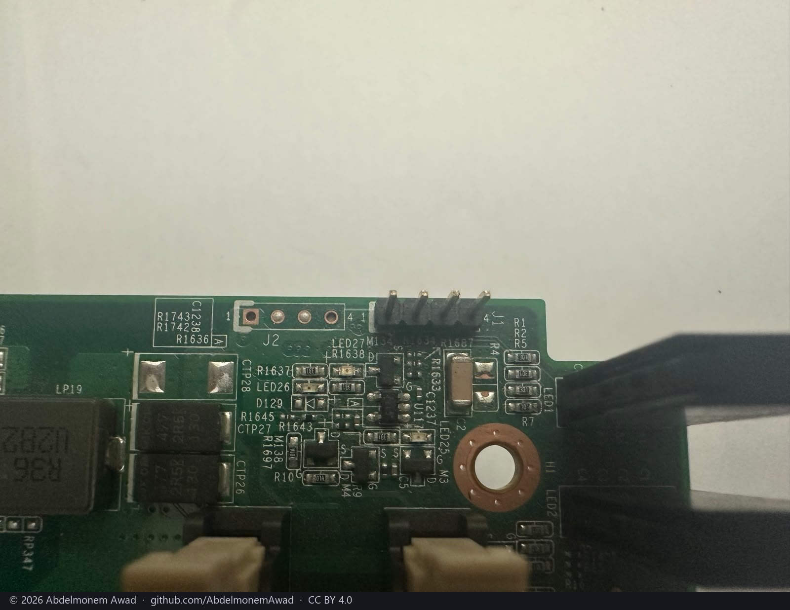
At the front edge: J1, a four-pin header, J2, a four-pad footprint, and the front LEDs
LED25 to LED27 with their drivers. Not traced.
The markings, in one table
| part | marking as photographed | designator | what it is | read from |
|---|---|---|---|---|
| the assembly | XGS 136w VER:C; AMDA0201 on the label |
- | the board, assembled in Taiwan | the label; the EEPROM and the SMBIOS serial say the same |
| the coprocessor | Marvell CN9130-2200 |
- | the coprocessor; the kernel on it reports a CN9131 | software, confirmed by the marking |
| the coprocessor's DRAM | SK hynix H5AN8G6NCJ, four |
- | DDR4 around the coprocessor | marking |
| the second Marvell part | 88F8215-A0 |
- | the second CP115 that makes the CN9131 of a CN9130 | the marking and the port map; not a datasheet |
| an 8-pin Atmel part | Atmel | U25 |
an EEPROM | package and marking only |
| the quad PHY | Marvell AQrate AQR412C-B0-C |
- | behind labels 9 to 12 | the platform file, confirmed by the marking; crystal U19 |
| the switch | Marvell 88E6193X-BXB2 |
- | behind labels 1 to 8 and the cages | the platform file, confirmed by the marking |
| the host | AMD Ryzen Embedded |
- | the R1606G FreeBSD reports | software, confirmed by the marking |
| the Super I/O | Nuvoton NCT6779D |
U35 |
the hardware monitor a stock FreeBSD cannot see | the BIOS reads it; the marking confirms it is there |
| the BIOS flash | an 8-pin SPI flash, AMIBIOS sticker | BIOS1; BIOS1(1) not fitted |
the host's firmware | marking and silkscreen |
| the console transceiver | TI TRS213I |
U65 |
RS-232 on the host's console | marking |
| the PoE controller | PD6910481 |
U40 |
a Microchip PD69104, four ports, behind labels 11 and 12 | the marking only |
| the eMMC | SanDisk SDINBDG4-8G |
U53 |
8 GB; the coprocessor's root is on it | software (7.28 GiB, root on p3), confirmed by the marking |
| a SPI flash | Macronix | U12 |
beside the empty CN8 |
marking; not traced |
| the Mini PCIe socket | 52 contacts, keyed after pin 15, silkscreen 17 and 51 |
CN, the digit cut off |
empty; on a w board, the place of the integrated Wi-Fi 5 radio the datasheet gives | the photograph and the datasheet; not traced |
| the expansion bay's connector | a row numbered B1 to B32 |
CN8 |
the one expansion slot, by its position above the bay | silkscreen and position; not traced |
| headers | JP11 (2x4), JP12 (4 pins), JP13, JP14, J1 (4 pins), J2 (4 pads) |
- | the coprocessor's console header is one of them | silkscreen; not traced |
| the front LEDs | LED25 to LED27 |
- | the front indicators and their drivers | silkscreen; not traced |
What the vendor's own tools tell you
Useful mostly as a map of what is reachable and from where. Roughly half of the xgs-* tools on
the host are seven-line shell wrappers that ssh to the coprocessor over the management link -
which this repository's driver now brings up, so what limits them is the SFOS userland they expect
on the far side, not the link. The rest run on the host.
Two are worth naming:
- The USB-SPI flash tool is the one this repository's reset path is derived from. It also reads and writes the coprocessor's boot flash from the host, which means a bricked bootloader is recoverable without opening the case.
- The platform-init tool is not a bring-up tool despite the name. It probes I2C busses 0-7 at
address
0x57for the baseboard VPD EEPROM and builds a key-value database that everything else reads. FreeBSD hassmbus0on this board, so that database can be rebuilt natively - it is where the per-port MAC addresses, PHY labels and transceiver configuration come from.
The XGS 3300, the other appliance here, has its own page: xgs3300.md.
The discussion of this page is held in the project's GitHub Discussions. Showing it here loads giscus from giscus.app and GitHub, and writing in it needs a GitHub account - what that means.