The rest of the appliance, and what driving each piece would need
This project's subject is the coprocessor and its front ports. An XGS 3300 is more than that: a front panel with an LCD and twenty-odd indicators, a CPLD, a managed switch, four PHY types, a fail-to-wire relay, thermal sensors on two different buses, and a USB-to-SPI bridge. None of it works under OPNsense today.
Everything here is from the live inventory taken off this board while the vendor's firmware was running it, which is held outside this repository, plus what this driver has measured since. Each row says where the knowledge is, so nobody has to rediscover it.
One structural fact decides most of this page. The panel, the switch and the PHYs hang off the
coprocessor, not the host - and NetAgent's MDIO and GPIO opcodes, 0x41, 0x42 and 0x43, have
no handler on this board: they return an ACK with status 1. So there is currently no host-side
path to any of them. What is reachable from the host today is a much shorter list than the hardware
suggests.
Reachable from the host now
| Piece | What it is | What it needs |
|---|---|---|
| The LCD | an EZIO-300 style serial panel on /dev/ttyS1, driven by a proprietary lcdd rather than LCDproc. The line is 9600 baud, not the 2400 the vendor's own script names - see below - and the display is 20 columns by 2 lines |
a host UART, which FreeBSD sees as cuau1, and the panel's own protocol. The menu tree, the key codes and the fact that lcdd owns the port are all recorded. This is the one piece that needs nothing from the coprocessor. It paints: two lines of correct text were read off this panel on 2026-10-02, by LCDproc's hd44780 driver out of the separate os-frontpanel plugin and not by anything in this repository |
| Thermal sensors | READ FROM THE HOST since 2026-10-13: the CPLD's SMBus face at slave 0x60 on the FCH's main SMBus controller, the port the firmware leaves selected, answers read-byte-data when the controller is driven directly - intsmb(4)'s ENXIO was the instrument's, not the bus's (the sensors answer on the host's own bus, tools/sensors/xgs3300-sensors.c: CPU 50 C, NPU 69.6 C, inlet 28 C, fans 6,600 and 6,900 rpm). Before that: read through the CPLD, not a Nuvoton part. xgs-1us-sensors -a prints CPLD VERSION 0x05000008 and CPLD BLOCKID 0x0000b002 - byte for byte the CPLD's own registers 0x01 and 0x00 - and then CPU Temperature 45, NPU Temperature 64, INLET Temperature 26, Fan 0 speed 6900 and the power-supply good flags, all in one invocation |
the CPLD path above, and nothing else. xgs-nct is a register poke tool, not a sensor reader: with no arguments it answers "You must specify a device and register and may have an optional value to write." Scoping a Nuvoton hwmon driver would have been wasted work |
| The CPU's own sensor, and the FCH watchdog | two of FreeBSD's own drivers, tried on 2026-10-12 while a soak ran: amdtemp attaches as AMD Family 17h CPU On-Die Thermal Sensors on hostb0 and reads the die at 46.6 C, which is the CPU figure the CPLD path above reports from outside; amdsbwd attaches as AMD FCH Rev 41h+ Watchdog Timer at 0xfed80b00 |
amdtemp is loaded at every boot through OPNsense's own Thermal Sensors setting, which the plugin sets once (appliance-defaults.md), and the watchdog is not armed - arming it (watchdogd) is the owner's decision, because an armed watchdog resets a host that a long lock holds for too long |
| The MCP2210 bridge | USB-to-SPI, present on this board | already measured: all nine pins read as inputs, matching no board's hold or release mask, so it does not hold this coprocessor. The plugin's reset path is for ARMADA boards |
| The CPLD | nineteen registers, not eleven: twelve in 0x00-0x2f and seven more at 0x30, 0x31, 0x38-0x3c. 0x00 is a block id reading 0x0000b002 and 0x01 a version reading 0x05000008 - the same two words xgs-1us-sensors prints as its banner, which is how they are identified. 0x02 and 0x03 hold 0xa5a5a5a5 and 0x5a5a5a5a, a fixed pair that catches a wrong stride. 0x25 carries the SFP cage pin states |
driven, from the coprocessor - see the section below. npu0.cpld.location=spi:0:1:3 reads as SPI bus 0, chip select 1, mode 3, and the node is /dev/spidev0.1 on the coprocessor exactly as that says. It is not a host bus, and the two sibling keys that settle the notation - npu0.slotA.vpd=i2c1:1:0x50 and npu0.device1.mdio=mdio22:0:2 - are on the coprocessor too |
Behind the coprocessor, and currently unreachable
| Piece | What it is | What it needs |
|---|---|---|
| The panel LEDs, ten ports | driven by the 88E6193X switch itself, from MVL6193LEDcontrol=0xe3 per port plus a GPIO pair each - gpio:0:51:52 for phy0, 0:53:54 for phy1, upward |
two things, both on the far side: the switch's LED control over MDIO, and those GPIOs, which are on the coprocessor's gpiochip432, label gpio_thunderx, 80 pins. Platform GPIO 51 is sysfs 483 there. This is why the whole panel is dark under a foreign operating system |
| PortF1 and PortF2's LEDs | no LED key at all in the platform store, because the cages hang directly off BGX2 rather than behind the switch | the 88X5113's own LED registers. The vendor's xgs-led all <left> <right> lights them by hand - amber at low speed, blue at high - so the hardware and the path are fine; nothing drives them as an activity indication, and a light on a cage is not an instrument |
| The 88E6193X switch | the ten panel ports behind it, at npu0.device1.mdio=mdio22:0:2. Its per-port registers were read, for all eleven devices: every one answers reg3=0x1930, the switch identifying itself from silicon, with reg0 ranging over 0x0f4d, 0x0e0f, 0x0249 and 0x0e49. Its frame limit was read on 2026-10-12 with mvsw (contrib/mvsw): Port Control 2 bits [13:12], the jumbo mode of the vendor SDK's gprtSetJumboMode, is 1 = 2,048 bytes on all ten panel ports and 2 = 10,240 on port 0, the uplink to the coprocessor - so behind the switch a frame scripts/xgs/switch-jumbo.sh (the MTU is the LIF's) |
MDIO from the coprocessor, where xgs-ssh.sh "xgs-mdio -a 0 2 <dev>.<reg>" already works. The host-side failure has a cause and it is in the capture too: the host binary wants a /dev/uio* node the host does not have, so it fails with "Error opening mdio handle" |
| The 88X5113 PHY | F1 and F2 at mdio45:0:7 - clause 45, bus 0, address 7 - with F1 on slice 0 and F2 on slice 2, from npu0.phy10.MVL5113=mdio45:0:7:0 and npu0.phy11.MVL5113=mdio45:0:7:2. Its identity is measured: 1.2 = 0x002b and 1.3 = 0x0b45 compose a PMA part number of 0x002b0b45, and 1.0 = 0x2040, 4.0 = 0x204c. Address 9 answers 0xffff, so F2 is not at an address of its own |
the same MDIO path. There is a safe first write on the same part - the tool's own help names an LED scratch register at 1F.0xF434, which reads back 0x4444 |
| The AQR412C and MVL3610 | the other PHY types the platform knows, named in xgs-mdio's own help |
the same |
| The fail-to-wire relay | LANBYPASS=MVL_FTW on this model. npu0.phy0.ftwbump=1 and npu0.phy1.ftwbump=-1 put the copper bypass pair on Port1 and Port2. Its three registers are on the CPLD and have been read: 0x39 is 0, so ftwstatus (mask 0x30), ftwcmd (mask 0xf00) and ftwarm (bit 0) are all clear; 0x3a, the watchdog, is 0; 0x3b, the trigger, is 2. The relay is disarmed |
xgs-ftw, which writes. Never run here, and it should not be run casually: an armed relay changes what the appliance does when software stops. Reading the three registers is safe and is how the state above was established |
Not present, and worth knowing so nobody looks
- Expansion slot A is empty.
npu0.slotA.present=0, andxgs-eeprom -t 1:0x50answers "No such device or address" for its VPD. The tool and the key store agree.
And a correction, because this page had it wrong. npu0.bp0 was described here as a 10G bypass
pair belonging to that empty slot. It is not. It is the internal 10G link between the coprocessor
and the switch, and the key store says so in its own notation:
npu0.bp0.init_speed=10G
npu0.bp0.port0=0:8          device 0 is CN8365, so this is the coprocessor's port 8
npu0.bp0.port1=1:0          device 1 is 88E6193X, so this is switch port 0
npu0.bp0.port0.mac=<base+0x0c>      the thirteenth address of the unit's block
npu0.bp0.port1.mac=<base+0x0d>      and the fourteenth
npu0.device0=CN8365 and npu0.device1=88E6193X give the dev:port scheme, and every front port
reads 1:1 through 1:10 - all on device 1, the switch. A pair keyed 0:8 and 1:0 is therefore
one end on each chip, which is a link between them, not a relay in a slot. Switch port 0 reads
reg0=0x0f4d - linked, full duplex, above 1G - which an unpopulated slot's port would not.
It also names two netdevs this project could not explain. pport_l0 and pport_l0s0p0
carry exactly those two addresses - the last two of the unit's fourteen-address block - and they
appear nowhere else in the capture. So the two odd entries in the vendor's interface list are
the two ends of the backplane link.
The copper fail-to-wire pair is separately keyed, on npu0.phy0.ftwbump and npu0.phy1.ftwbump, so
bp here means backplane and not bypass. PORT_000 in worker_port_cnt being the switch uplink is
the same link seen from the fast path's side.
- Power over Ethernet does not apply.
xgs-poeandxgs-poe-116exist in the image; this model has no PoE. STATUS_LED=NOon this model, sostatusled_CPLD,xgs-led-eventandxgs-led-identifyare for other boards.
The CPLD is driven now, and it was holding two ports dark
This is the first piece on this page that has been driven rather than described. It is reached
from the coprocessor, not from the host, and it needed no new code: the vendor's own xgs-cpld and
xgs-sff are already in the coprocessor's image.
The protocol is eight lines of lib/xgs_spi_cpld.c in the BSP and is worth writing down, because
anything that has to reach the CPLD without those tools needs it:
/dev/spidev0.1, SPI mode 3, 3 MHz
read   write one byte (reg | 0x80), then read four bytes, big-endian
write  one five-byte transfer: (reg & 0x7f) then four bytes, big-endian
So every register is 32 bits wide, which is what makes 0x25 able to hold four cages' worth of
pins. Registers 0x00 and 0x01 answer 0x0000b002 and 0x05000008 - the block id and version
this page already recorded from the sensor tool's banner - so a read can be checked before anything
is believed, and a wrong stride is caught immediately.
What it was holding. npu0.phy8.pin.tx_disable=cpld:0x25.4 and npu0.phy9.pin.tx_disable=cpld:0x25.10
are the two 1G SFP cages' laser-enable pins. Both read set, so both lasers were off; the two 10G
cages' equivalents at bits 16 and 22 read clear, which is why those two always worked. Clearing the
two bits through the vendor's pin path brings one cage straight up at a gigabit:
The full decode of 0x25, the correction it forces to what was written here about those modules, and
the switch-side result are in octeon-tx.md.
How volatile it is, measured rather than assumed. The bit survives a coprocessor restart: after
a host reboot, which restarts the coprocessor, register 0x25 still read the value it had been
given and a populated cage linked without being touched. It also survives a module being pulled and
a different one put in.
What does not survive a module swap is the SERDES. The same module moved from one cage to the
other did not link, and both cages' clause-45 registers read identically - 0xf002 0x0058,
0xf003 0x0004, 0x2000 0x1140 - so it was not a configuration difference. Re-running the
SERDES bring-up on the cage now holding the module brought it up at a gigabit within seconds, and
the panel LED followed. So a cage has two gates in order: the CPLD bit once, and the SERDES again
after every insertion.
The sensors, and how far a FreeBSD host gets toward them
The first table calls the thermal sensors reachable from the host, on the strength of
xgs-1us-sensors -a printing them under the vendor's firmware. That is right about where they live
and wrong about how close this project is to them, so here is the whole picture.
They are a register bank on the CPLD, reached over SMBus rather than SPI. The BSP's
lib/xgs_1us_sensors.c opens an 8-bit-addressed device at slave 0x60, probing I2C bus 0 and
then bus 1, and confirms it by reading the same block id the SPI path reads - 0xb002. So it is one
chip with two ways in, and the map is small enough to write down:
| register | what |
|---|---|
0x07, 0x08 |
CPU temperature, low and high |
0x09, 0x0a |
NPU temperature, high and low |
0x0b, 0x0c |
inlet temperature, high and low |
0x0d, 0x0e |
fan 0 and fan 1 speed |
0x14 |
fan 0 under-speed flag; writing 1 clears it |
0x16 |
minimum fan speed |
Temperature is high + low * 0.125, and the inlet reading is signed - above 128 it has 255
subtracted. The fan registers are read several times and reconciled, because a tachometer read in
flight is not a speed.
A device does answer at 0x60 on the host's own SMBus. FreeBSD attaches intsmb0 to the AMD
FCH controller and smbus0 above it, and with smb.ko loaded a bus probe finds something:
A receive-byte returns a value. A read-byte-data - the transaction the map above needs - returns
ENXIO. Every address on that list answers a receive-byte with the same 0x02, which is what a
bus with nothing really driving it looks like as often as it is five devices.
What the vendor's host does differently is the part to chase. Under SFOS the x86 side loads
i2c_piix4, which exposes both of the FCH's SMBus ports, and the BSP probes bus 0 and bus 1
precisely because the chip is not always on the first one. FreeBSD's intsmb attaches one
controller. So the next step is not a sensor driver; it is finding out whether the second port is
reachable here at all, and that is worth doing because it is the only peripheral on this page that
would need nothing from the coprocessor if it were.
A third road, walked 2026-10-12: the FCH's four multiplexed SMBus ports
This FCH (1022:790b rev 0x61, the kind whose host registers are in MMIO at 0xfed80a00)
selects among four SMBus ports through PMIO register 0x02, bits 4:3 - the same register and
shift Linux's i2c-piix4 uses for the KERNCZ family. Written from userland through the
0xcd6/0xcd7 index pair (a twenty-line reader on the bench, not in this repository), with smb.ko loaded and smbmsg
on /dev/smb0:
| port | what smbmsg -p finds |
at slave 0x60 |
|---|---|---|
| 0, as found | 0x60, 0x62, 0x66 answer a receive-byte |
every address answers 0x02; read-byte-data, write-byte-data and send-byte all ENXIO - the undriven-bus answer |
| 1 | nothing | ENXIO to everything, receive-byte included |
| 2, 3 | nothing | - |
Port 0 put back after. So the second port of the mux - the first guess above - is not where the
sensors are, nor the third or fourth. The host controller block itself reads live
(06 00 08 00 61 ff 00 00 10 00 00 00 00 00 b0 00 at 0xfed80a00), and the sixteen bytes after
it, where a second host controller would sit, read all zeros. What is left on the host side is
the FCH's auxiliary (ASF) controller, which Linux's i2c-piix4 registers as its own adapter and
which is what "bus 1" is to the BSP's xgs_1us_sensor_open; whether this platform's firmware
enables it, and where its registers are on this FCH generation, was not settled.
Two roads to the sensors that are now closed, so nobody walks them again
The SPI face does not carry them. It is the same chip by block id, but not the same register space, and reading the sensor offsets over SPI says so plainly:
0x00  0x0000b002      0x01  0x05000008      the block id and version, as expected
0x07  0xffffffff      0x08  0x082471e0      0x0a  0x00000098      0x0c  0x000000a0
0x09  0xfeedbeef      0x0d  0xfeedbeef      0x0e  0xfeedbeef      0x16  0xfeedbeef
0xfeedbeef is this CPLD's answer for a register that is not there, and it lands on four of the
seven sensor offsets. The SPI side is 32 bits wide and has its own map; the sensor map is the 8-bit
one behind the SMBus face.
And the coprocessor's own I2C buses do not reach it. /dev/i2c-0 and /dev/i2c-1 exist there,
i2cget, i2cset, i2cdetect and i2cdump are all in /sbin, and slave 0x60 answers on
neither:
bus 0:  0x00=Error: Read failed   0x01=Error: Read failed
bus 1:  0x00=Error: Read failed   0x01=Error: Read failed
That is consistent with where the vendor's tool lives: xgs-1us-sensors is an x86-64 binary and
is not in the coprocessor's image at all.
And the host's own SMBus does not have it either, on either port. The AMD FCH has two, and both were found and driven:
I/O 0x0b00   02 00 04 00 6b 02 00 02 ...   the primary, the same block FreeBSD maps at 0xfed80a00
I/O 0x0b20   00 00 00 00 00 00 00 00 ...   a second, live register block - the FCH's other port
A read-byte-data to slave 0x60 on the primary comes back with the device-error bit set: the
address is not acknowledged. On the second port every register reads 0x00 - and so does every
register of slave 0x55, which nothing should answer at all, so that port completes transactions
without a device on the other end and its success means nothing.
The receive-byte that looked like five devices earlier on this page is explained by the same dump:
0x02 is the first byte of the controller's own register block, not data from any slave.
And the answer is two controllers, one of which FreeBSD does not attach
Three things settle where to look, and none of them needed the hardware.
The sensor reading was taken on the host. The sweep that produced it is in the capture, and the
line above it is not: the switch dump is wrapped in xgs-ssh.sh '...' to run on the coprocessor and
the sensor line is not wrapped at all. So xgs-1us-sensors -a ran on the x86 side, as its
architecture already suggested.
Linux claims two I/O ranges for the same driver:
Two controllers, not one controller with a port-select field. That matters because the field does
exist - i2c_piix4 switches it on Family 17h through the indexed PM register at 0xcd6/0xcd7 -
and it is a red herring here: selecting each of its four values in turn and reading 0x60 gives the
same answer every time.
And with a controller that is actually behaving, the first one has nothing on it at all. The earlier probes on this page were taken without aborting a stuck transaction, so after the first refusal every later read reported "host busy" and meant nothing. With a KILL and a status clear before each attempt:
base 0x0b00  slave 0x60   device error      slave 0x50   device error
base 0x0b20  slave 0x60   00 00 00          slave 0x50   00 00 00
0x50 is DIMM SPD, which exists on any x86 board carrying memory. The first controller refuses it,
so nothing is on that bus, and that holds with intsmb0 detached as well, so FreeBSD's driver
was never in the way. The second controller acknowledges everything with zeros, including addresses
that cannot exist - which is what an uninitialised controller does, not what a device does.
So the question is now precise: the chip is on the second FCH controller, FreeBSD attaches only
the first, and the second needs real initialisation before anything it says means anything. That is
a FreeBSD intsmb question rather than a hardware one. Issue #164.
The probes are on the appliance in /root/npu - smb2.c is the one with the working reset, and
every one of them is read-only against any device.
What the second controller actually says, and what the coprocessor gives instead
The zeros above were the data register. Reading the status register through the same transaction says more, and it says two different things about the two controllers:
base 0x0b00  slave 0x60   status 05   HOST_BUSY | DEV_ERR    a clean refusal: nothing is there
base 0x0b20  slave 0x60   status 09   HOST_BUSY | BUS_ERR    the bus itself failed
Both are real controllers rather than unclaimed address space, which the control proves: a write to
either one's registers reads back, while the range at 0x0b40 reads 0xff at every offset and
keeps nothing.
A full seven-bit scan of the first controller - every address from 0x08 to 0x77 - returns a
device error on every one of them. Not one address answers. So that bus is not a question of
looking in the wrong place; there is nothing on it.
And the second one does not answer a transaction at all - it ends in a bus error, on every address,
including ones no device could occupy. So attaching a second intsmb as things stand would gain
nothing, which narrows issue #164 rather than solving it: the question is no longer "attach the
other controller" but "why does the other controller's bus fail", and the candidates are the clock,
the pull-ups and an enable this host never performs.
The chip is not on the coprocessor's I2C either. xgs-i2c-reg -b 0 -d 0x60 and -b 1 both
answer "No such device or address" from the coprocessor's own shell, and there is no bus 2. So the
0x60 device is on an x86 bus by design - the BSP header says as much, "an API to allow simple
access from X86 to the 1US sensors that are in the CPLD" - and this host cannot see it.
What does work today, from the coprocessor, with the vendor's own tools:
xgs-phy-temperature 1 .. 7     45.000 C      the copper PHYs
xgs-phy-temperature 8, 9       no sensor     the 1G SFP cages
xgs-phy-temperature 10         52.250 C and 52.500 C      the 10G PHY, two dies
xgs-cpss-temperature 0         fails: the CPSS driver is not running on this coprocessor
sensors                        "No sensors found", and /sys/class/hwmon is empty
That is real thermal telemetry, taken on this appliance, without writing a line of code - and it is a different set of sensors from the CPLD's. The CPLD holds the CPU, NPU and inlet temperatures and the fan speeds; the PHYs hold their own.
And the two views of the CPLD are not the same address space, which is worth stating because
the obvious shortcut does not work. From the coprocessor over SPI, register 0x00 is the block id
0x0000b002 and 0x01 is the version 0x05000008, each a 32-bit word. From x86 over SMBus the
same chip is a byte array: the version is bytes 0x00-0x02 and the block id is bytes 0x03 and
0x04. So the temperature offsets 0x07/0x08 in the x86 map cannot be read across to the SPI
side, and a sweep of the SPI registers that exist bears that out:
0x00 0000b002   0x01 05000008   0x02 a5a5a5a5   0x03 5a5a5a5a
0x04 00000000   0x05 00000000   0x07 ffffffff   0x08 082471e0
0x0a 00000098   0x0b d8000000   0x0c 000000a0   0x25 00386aeb
0x30 3400a17f   0x31 00000000   0x38 0000000c   0x39 00000000
0x3a 00000000   0x3b 00000002   0x3c 00010001
Everything else in 0x00-0x3f reads 0xfeedbeef, which is this CPLD's way of saying there is no
register there. 0x25 is the SFP cage register this page already documents and 0x39-0x3b are
the fail-to-wire block, read-only here by choice. The rest are not named by anything in the BSP,
and naming them from their values would be guessing.
The board, photographed
Everything above was read over a wire. This is the same appliance opened, and three of these pictures settle a question that reading could not.
Serial numbers and barcodes are blurred by hand - the private-data checker skips .jpg by
design, so nothing in tools/ would have caught them.
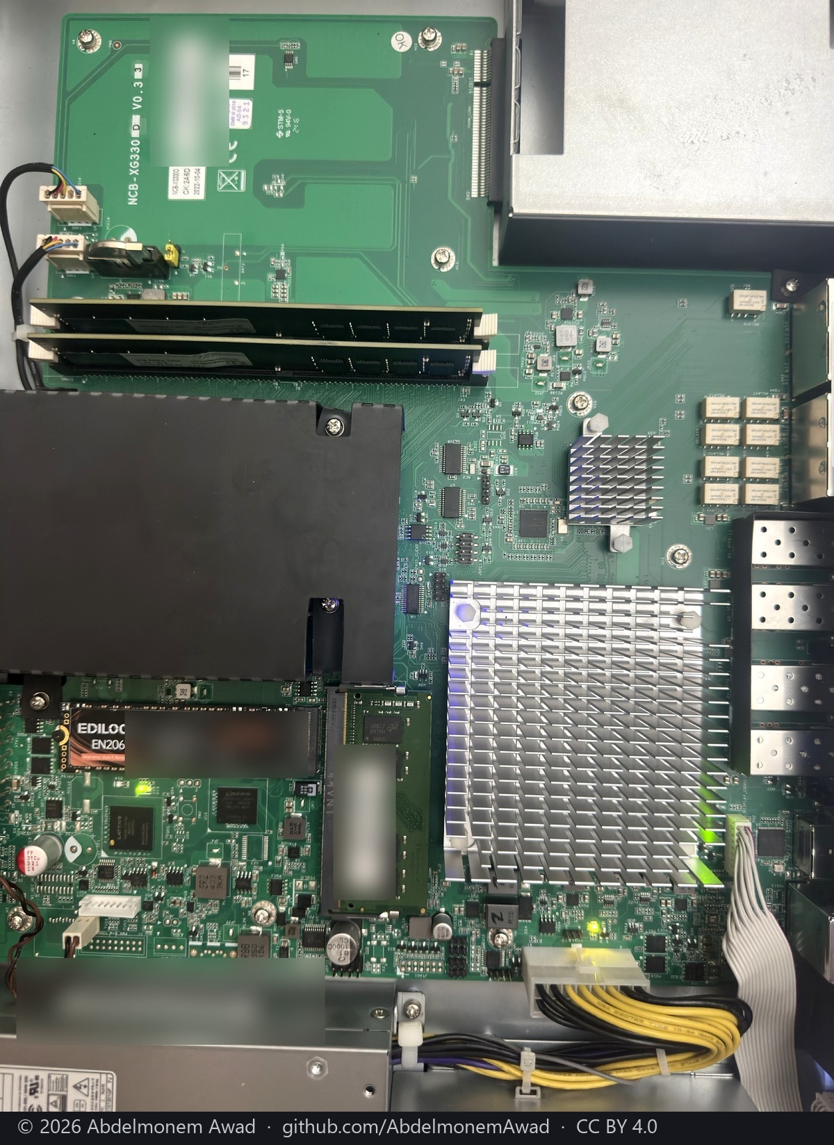
The daughterboard at the top is the coprocessor's carrier, and it carries its own name:
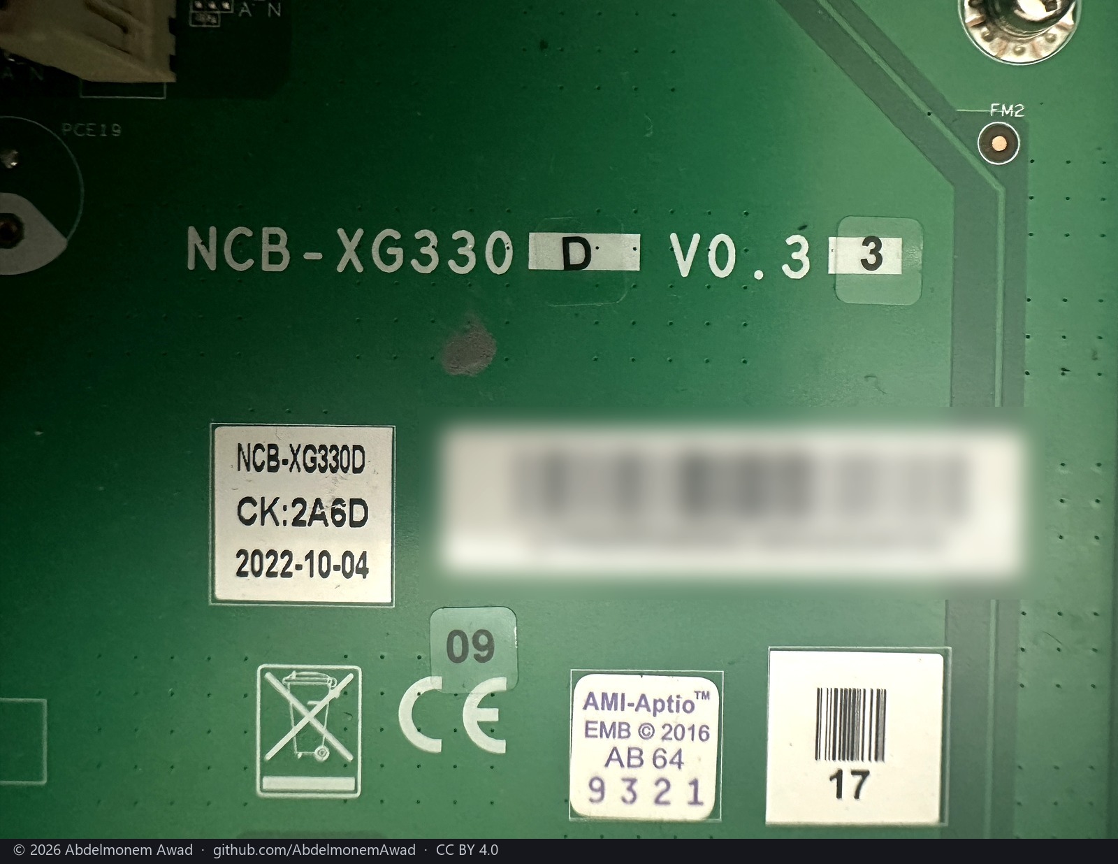
NCB-XG330D V0.3, dated 2022-10-04. Its barcode is the assembly this project has been quoting
from the firmware all along - AMDA0202-0004, revision 17 - so the carrier board of an XGS 3300 is
an engineering part named for the XG 330. The name on the silkscreen is not the name in the sales
catalogue, and anyone matching boards to models should know it.
And the CPLD is a Lattice part, with the vendor's own image beside it
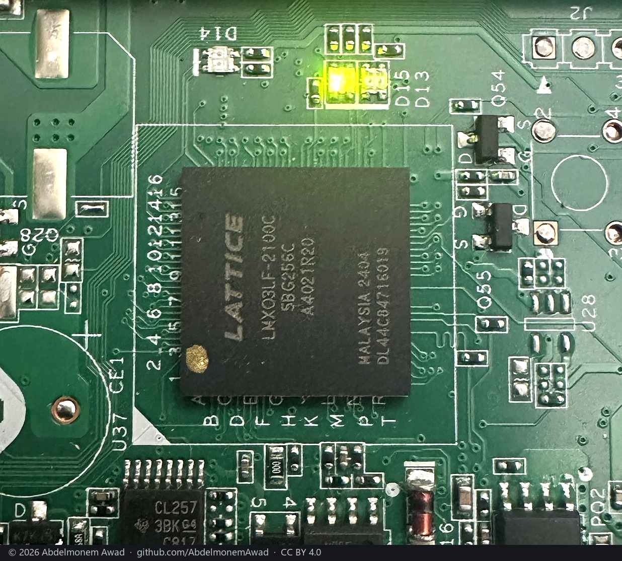
LATTICE
LCMXO3LF-2100C
5BG256C
MALAYSIA 2404
A MachXO3LF with 2,100 logic cells in a 256-ball BGA - an FPGA with its configuration flash on board rather than a CPLD in the old sense, which is why it answers a protocol of its own design over SPI with 32-bit registers.
And the vendor ships its image. npu-artifacts/cpld/ holds eight .vme files for this assembly
family, and .vme is Lattice's own deployment format. The header of the one whose name matches this
board says so plainly:
____12.1  Diamond Deployment Tool 3.11
CREATION DATE: Fri Oct 08 15:51:25 2021
The file is amda0202-0004r03_0x05000008.vme: assembly AMDA0202-0004, revision 03, version
0x05000008 - and 0x05000008 is exactly what register 0x01 reports on this appliance. The
name carries the board, the revision and the firmware version, and all three agree with what the
running part says about itself.
So the whole chain is now known: the part, the toolchain, the image, and a live register that matches the image's name. None of which is a reason to write it. The device holds the SFP cage pins, the fail-to-wire relays and the board's housekeeping; reprogramming it is how an appliance stops being one. It is documented so that nobody has to find it out, not so that anybody tries it.
The front panel has a controller of its own
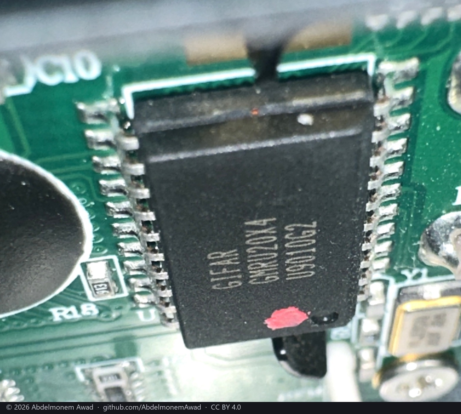
On the front panel board, beside its own crystal:
GIFAR
GMRU20X4
U9010G2
GI-FAR Technology is a display-module maker, and this part is the EZIO interface itself - a serial-to-HD44780 bridge implemented in a programmable micro-controller, which is exactly how the EZIO family is described. The LCD is not on the other end of that serial line. A micro-controller is, and the protocol is its own.
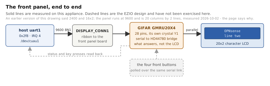
And that does not overturn the command set, which is worth saying plainly because it was
overstated here first. The vendor's own daemon sends 0xFE and then an HD44780 instruction to
this very panel, and it works. A bridge that accepts exactly that is what an EZIO device is. So the
instruction bytes read out of lcdd are not the open question, and the micro-controller does not
make them wrong.
What the micro-controller does change is where to look next - and the vendor's line setting, carried
one step further than it reads, is what settled it. stty ispeed 2400 sets the input speed only,
and uart1 is a 16450 with a single divisor, so on the vendor's own system that command never moved
the line: it sat at Linux's 9600 default. The panel runs at 9600. At 2400 it draws scattered
x-with-a-bar glyphs - HD44780 code 0xF8 - which is the signature of bytes arriving at a quarter of
the receiver's rate: the stretched start bit holds the first three sampled bits at zero and the next
stretched bit fills the remaining five with ones. At 9600 the text is legible, and two correct lines
were read off the panel on 2026-10-02.
**So 2400 was never this panel's rate, and reading the vendor's script literally is what kept issue
165 open for a week.** The instrument kept it open too: the rate sweep set the speed on the .init
device and then wrote through a fresh open, so what went on the wire was not what was being tested and every candidate looked wrong. What settled it opens the port once and sets the speed on the open descriptor.
And the display is 20 columns by 2 lines. Two lines from the vendor's own 0x28 function set,
and from a 20x4 ruler whose rows three and four landed on top of rows one and two; twenty columns
from counting glyphs in a photograph of a full row. So the 20 in GMRU20X4 is the width. What
painted it is the separate os-frontpanel plugin, through LCDproc's hd44780 driver with
ConnectionType=ezio - which fixes the line at 2400 on its own, so Speed=9600 has to be set
explicitly. Nothing in this repository has been seen painting the panel.
The fail-to-wire relays
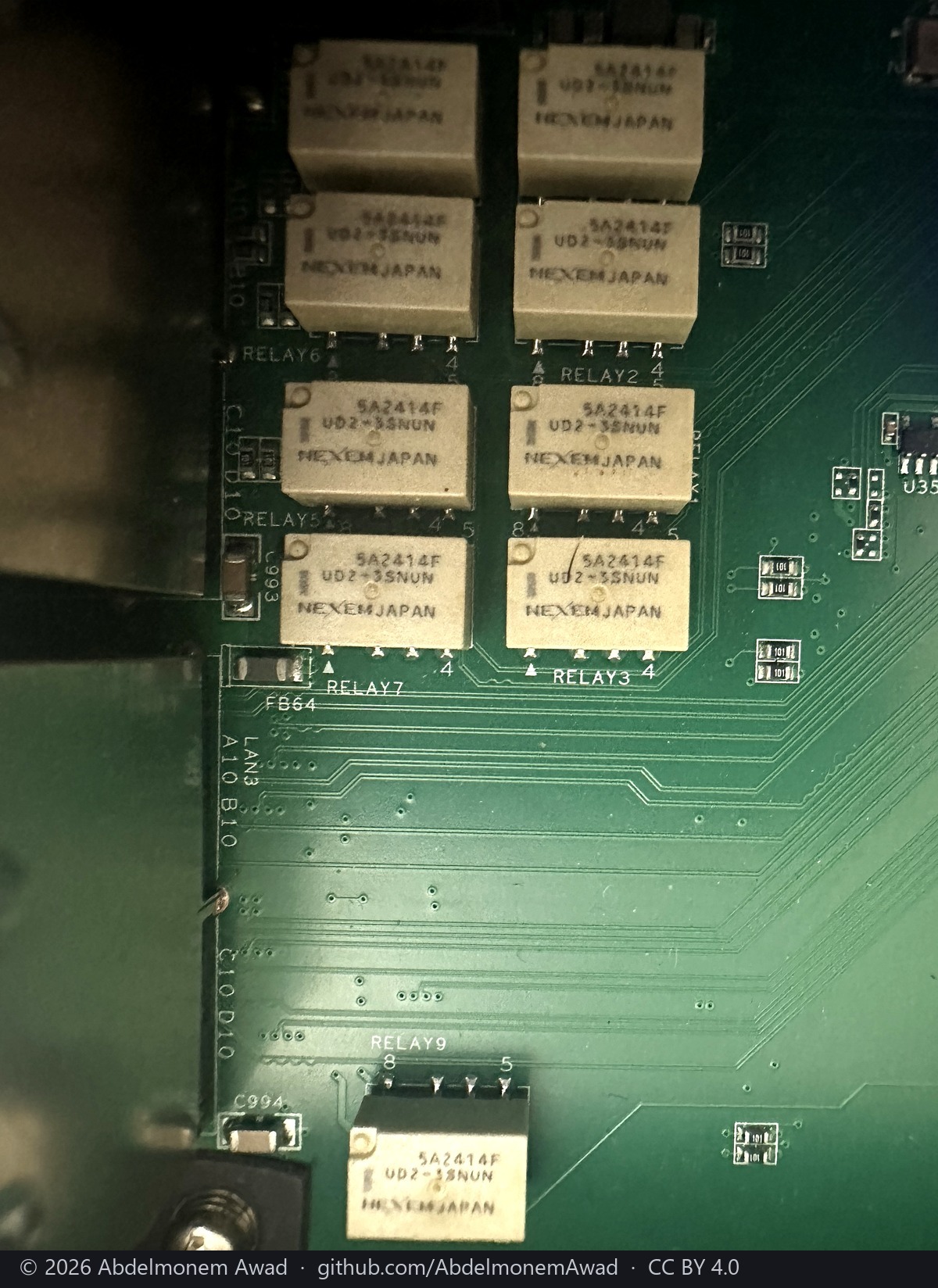
Nine of them, RELAY1 to RELAY9, each a NEXEM JAPAN UD2-3SNUN, 5A2414F - a two-form-C
signal relay. The silkscreen beside them names pairs, LAN3, A10 B10, C10 D10, which is what a
bypass pair looks like laid out: one relay per differential pair, two pairs per port.
This is the hardware behind CPLD registers 0x39, 0x3a and 0x3b, which this project reads and
has decided not to write.
The service headers
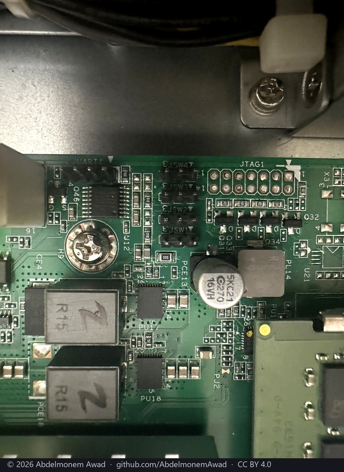
The board brings out more than the console. JUART1, JTAG1 and JTAG2, JSPI1 and JSPI2, four
selection jumpers JSW1 to JSW4, and one labelled PASS_CLEAR.
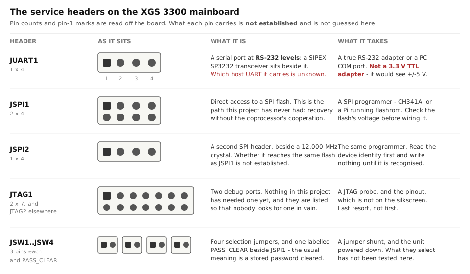
JUART1 is at RS-232 levels, not logic levels, and that matters before anything is plugged into
it: a SIPEX SP3232 transceiver sits immediately beside the header.
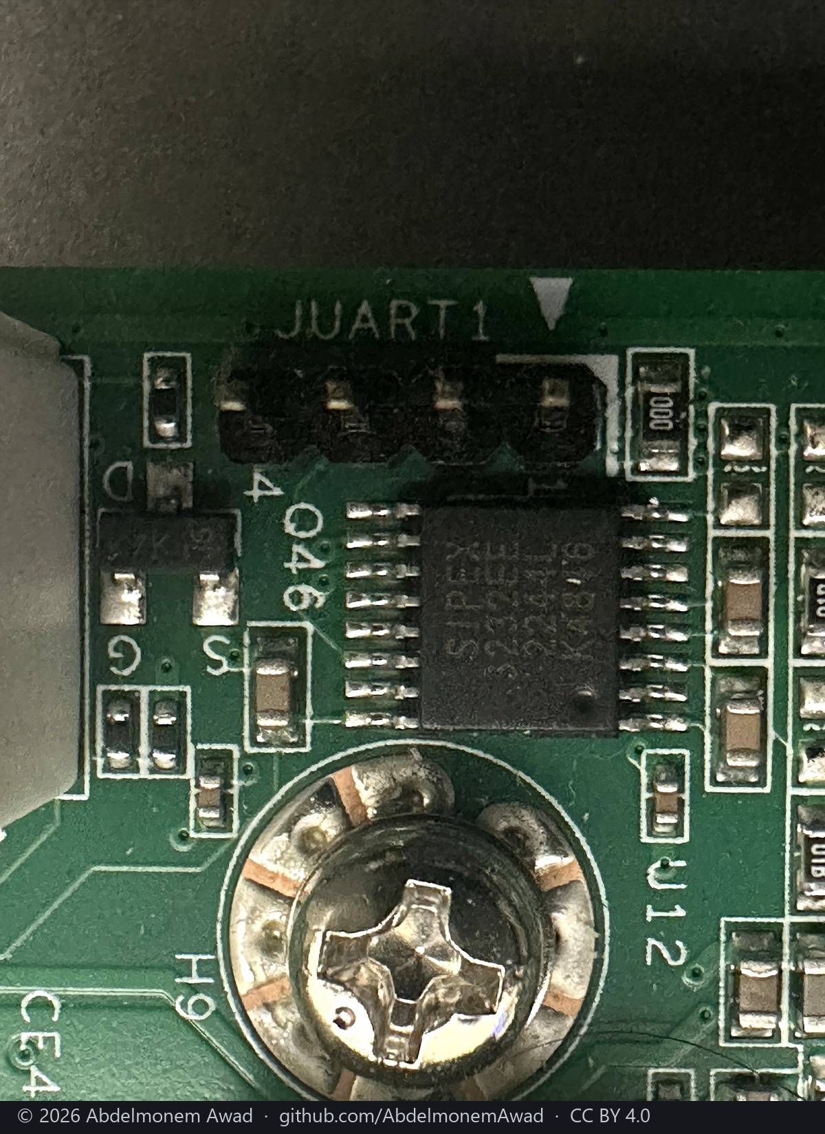
Which of the three host UARTs it carries - 0x3f8, 0x2f8 or 0x3e8 - is not established. The
way to find out needs no soldering: write a known pattern to each in turn and watch the pins.
JSPI1 and JSPI2 are the interesting pair. Recovery on this appliance has always needed the
coprocessor's cooperation, and the USB-SPI bridge was measured not to hold it - all nine pins read
as inputs. A header straight onto a SPI flash is a different road entirely, and it is the one worth
walking next.
And the management port's silicon
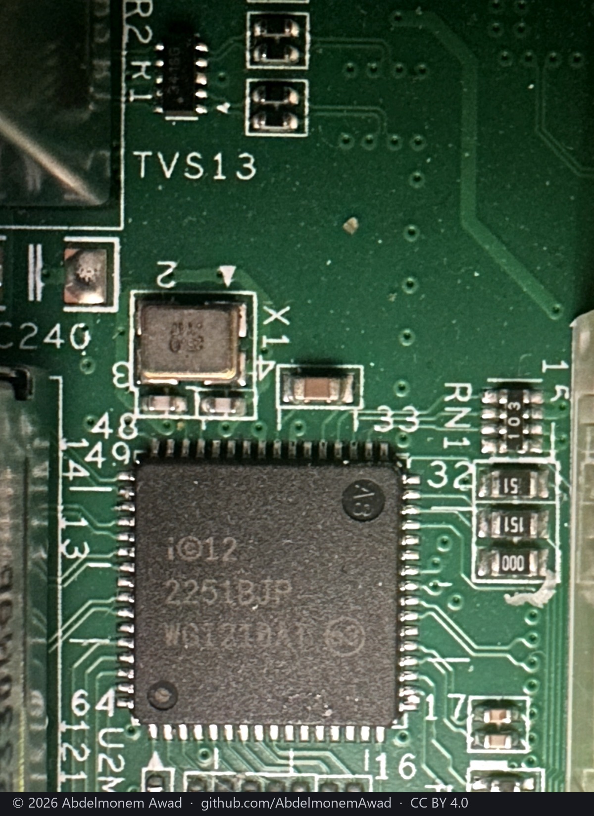
WGI210AT - the Intel i210-AT, which is 8086:157b at pci0:2:0:0 and igb0 under FreeBSD. It is
the only Intel part on the board.
flowchart LR
    C["AMD Ryzen V1780B"] -->|PCIe| I["Intel i210-AT - WGI210AT<br/>8086:157b at pci0:2:0:0"]
    I --> M["magnetics"] --> R["RJ45 PortMGMT"]
    I -.-> F["igb0 in FreeBSD"]
The front panel's protocol, read out of the vendor's own daemon
The LCD is the one piece here that needs nothing from the coprocessor. FreeBSD probes it as
uart1 at port 0x2f8 irq 4 - byte for byte the /dev/ttyS1 that lcdd drives - and nothing on
OPNsense claims it.
lcdd is proprietary and stripped, which is why this page said for weeks that the protocol would
have to be found some other way. It does not: the command bytes are not stripped. They sit in
.data and are written one at a time, the escape and then the instruction, through two write()
calls each. Disassembled on the appliance itself:
.data 0x8057030 = 0xfe     the escape, written before every instruction
      0x8057014 = 0x28     function set, two lines
      0x805701c = 0x01     clear
      0x8057018 = 0xc0     set address to the start of line two
      0x805702c = 0x06     entry mode, increment
      0x8057020 = 0x18     shift display left        0x8057024 = 0x1c   shift right
      0x8057028 = 0x40     set CGRAM address, for a custom glyph
and inline, where the compiler folded a pair into one store: movw $0x0dfe is FE 0D,
movw $0x0efe is FE 0E, and a three-byte write sends FE 58 FD.
So it is the HD44780 instruction set behind an 0xFE escape, which is what "EZIO-300" means
here. src/opnsense/scripts/panel/panel.sh is the host-side tool, and it opens the port once -
setting the speed on the .init device and then writing through a fresh descriptor is how the
first attempt sent its bytes at the wrong rate.
The ordering is the part worth keeping. The first attempt sent clear and line addressing with no function set in front of them, and the panel answered with a row of identical characters: a display that has not been told how many lines it has does not have a line two to address. The vendor's own order is function set, entry mode, display on, clear - and only then text.
What is read here is every byte above, and that is not in doubt. That this instruction set paints
this panel is no longer in doubt either: somebody stood in front of the appliance on 2026-10-02 and
read two correct lines off it. What painted them was LCDproc's hd44780 driver from the separate
os-frontpanel plugin, at 9600 baud - not this sequence from this repository, which has still never
been seen on the glass.
The order these are worth doing in
- The LCD. It is the only piece that needs nothing from the coprocessor, its port is an ordinary host UART, and the protocol is a serial panel rather than a register map. It is also the most visible thing an appliance can do while a driver is still being written.
The CPLD, over the coprocessor's SPI.Done - see the section above. It carries the SFP cage pin states and, on the evidence in this page's first table, the temperatures and fan speeds as well, so it was one piece of work rather than the three this list used to have. What remains is a host-side path to it, which today means going through the coprocessor.An MDIO path through the coprocessor, which unlocks the switch, all four PHY types and the panel LEDs at once. Done -contrib/mvswdrives the switch over/dev/mvmdio-uio, every panel port is forwarding and the panel LEDs are lit. NetAgent still cannot carry it, so this is still a coprocessor-side path and not a host-side one.- The LEDs on F1 and F2, which are the only indicators left dark: they hang off the 88X5113 rather than the switch, and the board file has no LED key for them at all.
- The fail-to-wire relay, last, and only deliberately. It is the one piece here whose wrong setting changes the appliance's behaviour when nothing is running.
What this page is not
It is not a claim that all of it works. Two rows have now been driven - the CPLD and, through it, the SFP cages, plus the switch over MDIO - and each says so where it is claimed. Everything else in the two tables is still description, and the repository's rule is that nothing is claimed that has not been run. Note also what "driven" means here: from the coprocessor's own shell, not from OPNsense. The value here is that the measurements exist, they were taken on this board under the firmware that does drive all of it, and the next person does not have to start by finding out which bus a part is on.
The discussion of this page is held in the project's GitHub Discussions. Showing it here loads giscus from giscus.app and GitHub, and writing in it needs a GitHub account - what that means.